CTB Vacuum Circuit Breaker Operating Mechanism


Description
The CTB vacuum circuit breaker operating mechanism is aquality machinery that could be matched with the ZW32-12/24 outdoor highvoltage vacuum circuit breaker and other similar outdoor or indoor vacuumelectrical switchgear.It can meet the authoritative standard of GB
Ambient Condition ofthe CTB vacuum circuit breaker operating mechanism
1. Surrounding air temperature:
2. Altitude: under
3. Relative humidity: under 95%(daily average), 90%(month average);
Vapor pressure: under 2.2Kpa (dailyaverage), 1.8Kpa(month average);
4. No frequent serious vibration, water vapor, gas, chemical corrosive deposit,salt mist, dust, fire nor explosive materials which substantially undermine themechanism’s performance.
Weight of the CTB Vacuum Circuit BreakerOperating Mechanism
CTB-S:
Structure and Working Principles
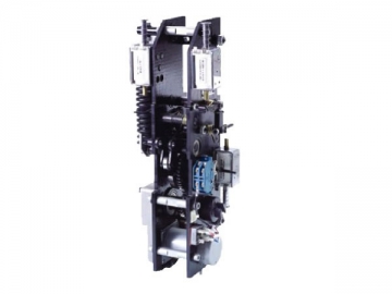
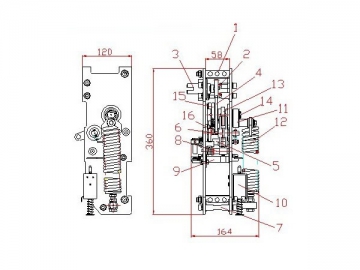
Structure ofCTB-S
image001.jpg
1. mounting posts; 2. pinion; 3. storageshaft;
4. main gear; 5. closingaxle; 6. outputcrank arm;
7. supporting column; 8. tripping pawl
10. over-current coil; 11. energystorage crank arm;
12. energy storage spring;
14. main axis; 15. wheelgear; 16. clutchplate;
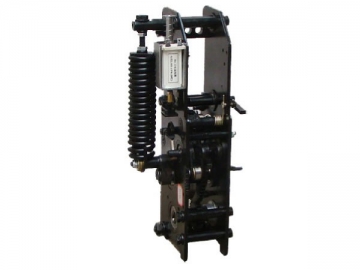
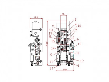
Structure of CTB-D
image002.jpg
1.mounting posts; 2. motor; 3. mainaxis;
4. energy storage axis; 5. pinion; 6. energystorage crank arm;
7. output crank arm; 8. wheelgear; 9. trippingpawl;
10. tripping axle; 11. trippingcoil; 12. over-current coil;
13. tripping spring; 14. closingspring; 15.closing pawl;
16. cam; 17.
18. wheel gear; 19. closingcoil.


")

")


