GFNS3 FRP Counterflow Cooling Tower with Reinforced Concrete Frame

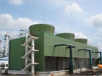
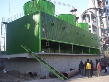

Our GFNS3 FRP counterflow cooling tower comes with a reinforced concrete frame. It can efficiently transfer the waste heat in cooling water to the atmosphere. The features of this cooling system include good heat conductivity, low energy consumption, and so on. The cooling water capacity ranges from 800 m3/H to 3000 m3/H.
Application
The FRP counterflow cooling tower is mainly used as the cooling and refrigeration system in many areas like injection molding, leatherworking, power generation, steam turbine cooling, section aluminum processing, air compressor, industrial water cooling, and so on. Generally, the applications fall under three categories.
A. Air conditioning system: air conditioner, refrigeration house, freezing house, HVAC system, etc.
B. Manufacturing and processing: food processing, medicine processing, metal forging, plastic industry, rubber industry, textile industry, steel company, chemical industry, petrochemical industry, and so on.
C. Cooling system for mechanical device: generator, steam turbine, air compressor, oil press, engine, etc.
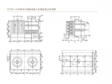
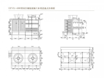
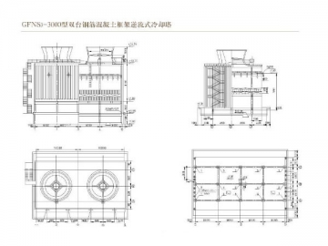
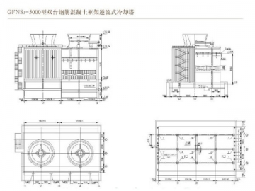
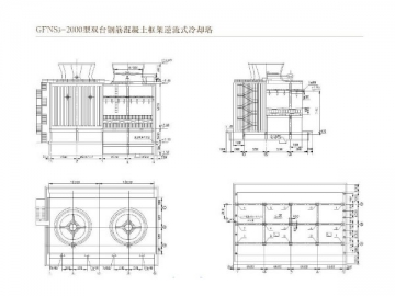
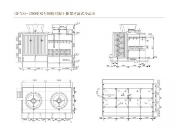
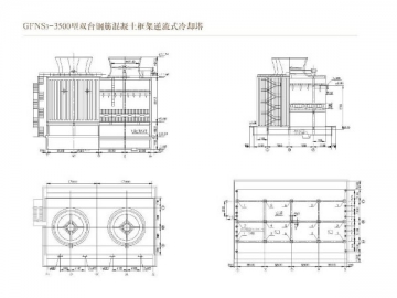
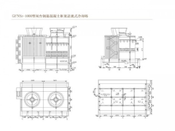
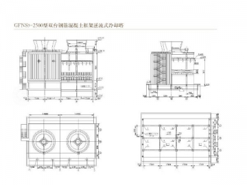
1. Product Structure
This product is comprised of these following parts, FRP duct, motor, draught fan, speed reducer, modified filler, water collecting device, water distribution system, FRP protective panel, concrete framework, etc.
2. Main Features
1) Our motor has an adjustable torque and speed. Such design guarantees not only good thermal performance, but also energy saving of 40-52%, leading a domestic and international level.
2. We have made some adjustment to our cooling tower. One is that the stand column of air inlet has been moved inward 1-2.5m, letting the air directly into the spraying filler and avoiding the vortex in the air inlet. The other is that the height of tower has been reduced by 0.5-0.9 m, guaranteeing uniform inlet wind and higher cooling capacity. It also prevents the frozen damage of reinforced concrete beams and columns.
3) Stable performance and long lifespan: Each trapezoid part is 23mm high, remarkably reducing the wind resistance, increasing the filler height from 1.0m to 1.5m and improving the thermal performance.
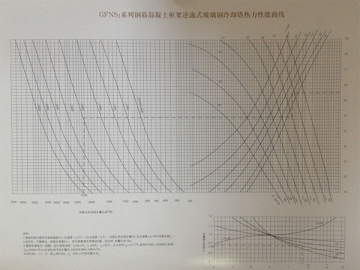
3. Parameter of Concrete Reverse-Flow Cooling Tower
Cooling capacity: 800~5,000 m3/h
Temperature of inlet water: 42 ℃
Temperature of outlet water: 32℃
Wet bulb temperature: 28℃
Dry bulb temperature: 31.5℃
Cooling temperature difference: 4 ℃
Temperature difference: 10℃
Atmosphere pressure: 100,400 Pa
Voltage: 380V, 50Hz
Pressure of inlet water: 1.0~1.5*104Pa
| GFNS3-800 | GFNS3-1000 | GFNS3-1200 | |||||||||
| NO. | Item | Data | unit | NO. | Item | Data | Unit | NO. | Items | Data | Unit |
| 1 | Cooling capacity | 800 | m³/h | 1 | Cooling capacity | 1000 | m³/h | 1 | Cooling capacity | 1200 | m³/h |
| 2 | Cooling temperature difference | 4 | ℃ | 2 | Cooling temperature difference | 4 | ℃ | 2 | Cooling temperature difference | 4 | ℃ |
| 3 | Temperature difference | 10 | ℃ | 3 | Temperature difference | 10 | ℃ | 3 | Temperature difference | 10 | ℃ |
| 4 | Weight of draught fan | 547 | kg | 4 | Weight of draught fan | 547 | kg | 4 | Weight of draught fan | 1520 | kg |
| 5 | Weight of Motor | 368 | kg | 5 | Weight of Motor | 590 | kg | 5 | Weight of Motor | 620 | kg |
| 6 | Wind volume | 6.x100000 | m³/h | 6 | Wind volume | 7.8x100000 | m³/h | 6 | Wind volume | 9.x100000 | m³/h |
| 7 | Total pressure | 132.4 | Pa | 7 | Total pressure | 148 | Pa | 7 | Total pressure | 138 | Pa |
| 8 | Static pressure | 98 | Pa | 8 | Static pressure | 95 | Pa | 8 | Static pressure | 95 | Pa |
| 9 | Diameter of impeller | 4700 | mm | 9 | Diameter of impeller | 4700 | mm | 9 | Diameter of impeller | 5460 | mm |
| 10 | Rotating speed of impeller | 240/180 | r/min | 10 | Rotating speed of impeller | 240/180 | r/min | 10 | Rotating speed of impeller | 165/109/83 | r/min |
| 11 | Installing angle | 13.5 | degree | 11 | Installing angle | 20 | degree | 11 | Installing angle | 18 | degree |
| 12 | Power | 30/15 | kw | 12 | Power | 45/22 | kw | 12 | Power | 45/15/7.5 | kw |
| 13 | Rotating speed of motor | 960/730 | t/min | 13 | Rotating speed of motor | 960/750 | t/min | 13 | Rotating speed of motor | 1450/960/730 | t/min |
| 14 | Standard sound level | High speed | dB(A) | 14 | Noise standard | High speed | dB(A) | 14 | Standard sound level | High speed | dB(A) |
| 15 | Low speed | dB(A) | 15 | Low speed | dB(A) | 15 | Low speed | dB(A) | |||
| 16 | Number of impellers | 4 | Pieces | 16 | Number of impellers | 4 | Pieces | 16 | Number of impellers | 6 | Pieces |
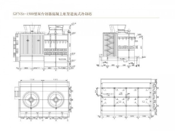
| GFNS3-1500 | GFNS3-2000 | GFNS3-2500 | |||||||||
| NO. | Items | Data | Unit | NO. | Items | Data | Unit | No. | Items | Data | Unit |
| 1 | Cooling capacity | 1500 | m³/h | 1 | Cooling capacity | 2000 | m³/h | 1 | Cooling capacity | 2500 | m³/h |
| 2 | Cooling temperature difference | 4 | ℃ | 2 | Cooling temperature difference | 4 | ℃ | 2 | Cooling temperature difference | 4 | ℃ |
| 3 | Temperature difference | 10 | ℃ | 3 | Temperature difference | 10 | ℃ | 3 | Temperature difference | 10 | ℃ |
| 4 | Weight of draught fan | 1540 | kg | 4 | Weight of draught fan | 2420 | kg | 4 | Weight of draught fan | 2420 | kg |
| 5 | Weight of motor | 1000 | kg | 5 | Weight of motor | 1190 | kg | 5 | Weight of motor | 1680 | kg |
| 6 | Wind volume | 12x100000 | m³/h | 6 | Wind volume | 16x100000 | m³/h | 6 | Wind volume | 20x100000 | m³/h |
| 7 | Total pressure | 156.9 | Pa | 7 | Total pressure | 160 | Pa | 7 | Total pressure | 170 | Pa |
| 8 | Static pressure | 110 | Pa | 8 | Static pressure | 113 | Pa | 8 | Static pressure | 120 | Pa |
| 9 | Diameter of impeller | 6000 | mm | 9 | Diameter of impeller | 7000 | mm | 9 | Diameter of impeller | 8000 | mm |
| 10 | Rotating speed of impeller | 165/109/83 | r/min | 10 | Rotating speed of impeller | 149/112/75 | r/min | 10 | Rotating speed of impeller | 149/112/75 | r/min |
| 11 | Installing angle | 17 | degree | 11 | Installing angle | 15 | degree | 11 | Installing angle | 9 | degree |
| 12 | Power | 75/25/12.5 | kw | 12 | Power | 110/55/18.5 | kw | 12 | Power | 132/66/22 | kw |
| 13 | Motor Speed | 1450/960/730 | t/min | 13 | Motor SPeed | 960/730/480 | t/min | 13 | Motor Speed | 960/730/480 | t/min |
| 14 | Standard sound level | High speed | dB(A) | 14 | Standard sound level | High speed | dB(A) | 14 | Standard sound level | High speed | dB(A) |
| 15 | Low speed | dB(A) | 15 | Low speed | dB(A) | 15 | Low speed | dB(A) | |||
| 16 | Number of impellers | 6 | Piece | 16 | Number of impellers | 6 | Piece | 16 | Number of impellers | 6 | Piece |
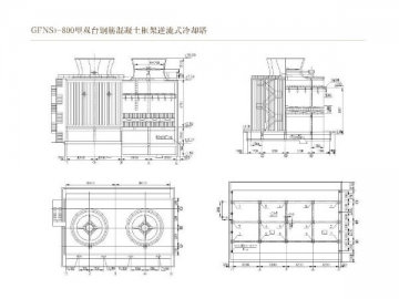
| GFNS3-3000 | GFNS3-3500 | GFNS3-4000 | |||||||||
| NO. | Items | Data | Unit | NO. | Items | Data | Unit | NO. | Items | Data | Unit |
| 1 | Cooling capacity | 3000 | m³/h | 1 | Cooling capacity | 3500 | m³/h | 1 | Cooling capacity | 4000 | m³/h |
| 2 | Cooling temperature difference | 4 | ℃ | 2 | Cooling temperature difference | 4 | ℃ | 2 | Cooling temperature difference | 4 | ℃ |
| 3 | Temperature difference | 10 | ℃ | 3 | Temperature difference | 10 | ℃ | 3 | Temperature difference | 10 | ℃ |
| 4 | Weight of draught fan | 2490 | kg | 4 | Weight of draught fan | 4850 | kg | 4 | Weight of draught fan | 4850 | kg |
| 5 | Weight of motor | 1380 | kg | 5 | Weight of motor | 1700 | kg | 5 | Weight of motor | 1800 | kg |
| 6 | Wind volume | 24x100000 | m³/h | 6 | Wind volume | 27.3x100000 | m³/h | 6 | Wind volume | 31.5x100000 | m³/h |
| 7 | Total pressure | 164 | Pa | 7 | Total pressure | 170 | Pa | 7 | Total pressure | 160 | Pa |
| 8 | Static pressure | 110 | Pa | 8 | Static pressure | 116 | Pa | 8 | Static pressure | 104 | Pa |
| 9 | Diameter of impeller | 8530 | mm | 9 | Diameter of impeller | 9140 | mm | 9 | Diameter of impeller | 9140 | mm |
| 10 | Rotating speed of impeller | 149/112/75 | r/min | 10 | Rotating speed of impeller | 110/82/55 | r/min | 10 | Rotating speed of impeller | 149/112/75 | r/min |
| 11 | Installing angle | 8 | degree | 11 | Installing angle | 15 | degree | 11 | Installing angle | 16 | degree |
| 12 | Power | 132/66/22 | kw | 12 | Power | 160/80/30 | kw | 12 | Power | 160/80/30 | kw |
| 13 | Motor Speed | 960/730/480 | t/min | 13 | Motor Speed | 960/730/480 | t/min | 13 | Motor Speed | 960/730/480 | t/min |
| 14 | Standard sound level | High speed | dB(A) | 14 | Standard sound level | High speed | dB(A) | 14 | Standard sound level | High speed | dB(A) |
| 15 | Low speed | dB(A) | 15 | Low speed | dB(A) | 15 | Low speed | dB(A) | |||
| 16 | Number of impellers | 6 | Piece | 16 | Number of impellers | 8 | Piece | 16 | Number of impellers | 8 | Piece |


")
")
")
")
")
")


