Polarization-Maintaining Fiber Optic Coupler
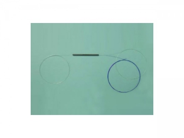
Pictures and Schematic Diagram
The polarization maintaining fiber optical coupler, also called PM optic fiber coupler, is made with polarization-maintaining optic fiber which has been subjected to fused biconical taper process. It is a commonly seen fiber optic component on optical sensors and optical gyroscopes. Its coupling ratio can be decided by customers.
Features of PM Fiber Optic Coupler
Good Uniformity and Low Insertion Loss
Low Polarization Dependent Loss
Various Coupling Ratio
Excellent Environmental Stability
Outstanding Mechanical Properties
Stability: Telecordia GR-1221 and GR-1209 compliant
Applications of PM Fiber Optic Coupler
Fiber Optic Sensors
Passive Optical Networks(PON)
Local Area Networks (LAN)
CATV Systems
Fiber to the Subscriber (FTTx) applications
Test Equipment
Technical Specifications of Polarization-Maintaining Fiber Optic Coupler
| Parameter | 1´2, 2´2 | ||||||||||
| Operating wavelength(nm) | 780, 850 | 98, 1060 | 1310, 1480, 1550 | ||||||||
| P grade | A grade | P grade | A grade | P grade | A grade | ||||||
| Coupling Ratio | 50/50, 30/70, 20/80, 10/90, 5/95, 3/97, 2/98, 1/99 | ||||||||||
| Max. Excess Loss(dB) | ≤0.6 | ≤0.8 | ≤0.4 | ≤0.6 | ≤0.3 | ≤0.4 | |||||
| Max. Uniformity(dB) | ≤0.8 | ||||||||||
| Min. Extinction Ratio(dB) | ≥20 | ≥18 | ≥20 | ≥18 | ≥20 | ≥18 | |||||
| Optical Return Loss(dB) | ≥50 | ||||||||||
| Power Handling (mW ) | 500 | ||||||||||
| Max. Tensile Load(N) | 5 | ||||||||||
| Operating Temperature (℃) | -5~ 70 | ||||||||||
| Storage Temperature (℃) | - 40~ 85 | ||||||||||
| Fiber Type | PM PANDA Fiber(125/245um) | ||||||||||
| Package Dimension(mm) | 3×54 or longer | ||||||||||
| Coupling Ratio | Insertion Loss (dB) | ||||||||||
| 780,850 | 980 1060 | 1310, 1480, 1550 | |||||||||
| P grade | A grade | P grade | A grade | P grade | A grade | ||||||
| 50/50 | ≤3.8 | ≤4.0 | ≤3.6 | ≤3.8 | ≤3.4 | ≤3.6 | |||||
| 30/70 | / | ∕ | ≤5.75/2 | ≤6.1/2.1 | ≤5.6/1.9 | ≤5.75/2 | |||||
| 20/80 | ≤8.2/1.7 | ≤8.5/1.9 | ≤8.0/1.5 | ≤8.2/1.7 | ≤7.6/1.4 | ≤8.0/1.5 | |||||
| 10/90 | ≤11.8/1.4 | ≤12.0/1.6 | ≤11.6/1.2 | ≤11.8/1.4 | ≤11.2/0.85 | ≤11.6/1.0 | |||||
| 5/95 | ≤15.0/1.0 | ≤15.2/1.2 | ≤14.8/0.8 | ≤15.0/1.0 | ≤14.2/0.6 | ≤14.8/0.8 | |||||
| 3/97 | ∕ | ∕ | ≤16.57/0.45 | ≤17.12/0.6 | ≤15.2/0.4 | ≤15.8/0.5 | |||||
| 2/98 | ∕ | ∕ | ≤18.4/0.35 | ≤18.9/0.5 | ≤16.8/0.35 | ≤17.4/0.45 | |||||
| 1/99 | ≤22.5/0.6 | ≤22.8/0.8 | ≤22.0/0.4 | ≤22.5/0.6 | ≤21.5/0.3 | ≤22/0.4 | |||||
Note: For fiber optic devices with connectors, the insertion loss is 0.3dB higher than those without connectors. Besides, their RL is 5dB lower, and ER is 2dB less. The keyway of the connector is aligned with the slow axis.
Order Information
COU-A-B-C-D-E-F-G-H-I-J


")


")


")

")
")
 Optical Switch")


