Desiccant Air Dryer


Regenerated Air Dryer
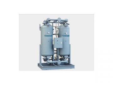
CWPH - Heatless Regenerated Dryer (120-1800 cfm)
A heatless desiccant dryer is frequently the best selection for drying small quantities of air to a -40°F or-100°F dew point, or for drying intermittent flows. Heatless dryers are also useful for drying in hazardous environments.
Desiccant dryers have the following advantages over heated types:
1) Lower cost than heat reactivated units
2) Require no high voltage power (saves on electrical installation and service expenses)
3) Operates at low temperatures
4) Not a fire or safety hazard
The CWPH units find applications in mines, process industries, off-shore platforms and drilling rigs. The CWPH dryer is best suited to large volume users of very dry air. The CWPH can be customized to best match end user requirements. The CWPH is designed for simple operation and maintenance.
DESICCANT - High strength 1/4" activated alumina.
PREFILTER - A high-efficiency (HC) coalescing filter is factory-mounted on the dryer package or shipped loose for field mounting. The compressed air is pre filtered prior to entering the dryer's drying vessel to collect any contaminants such as dirt, water or oil drop lets from the upstream compressor. The filter has a 0.01 micron and 0.01 ppm rating.
AFTERFILTER - A particulate, (HT) filter is factory-mounted on the dryer package or shipped loose for field mounting. The compressed air is filtered downstream from the drying vessel to collect any dusting that may have occurred as a result of the drying process. The filter has a 1.0 micron rating.
AUTOMATIC DRAIN VALVE - Supplied on the prefilter of every dryer, this is a mechanical float operated drain valve. A no-loss drain or electronic drain can be provided as a shipped-loose option. Larger dryers are equipped with automatic drain valves.
FILTER DIFFERENTIAL PRESSURE INDICATORS - These are included on pre- and afterfilters to monitor the condition of filter elements.
* For maximum energy efficiency it is recommended to change prefilter and afterfilter elements every year or when they indicate restricted flow.
DRYING VESSELS - Of welded steel construction, all CWPH models are GB or ASME code stamped. Removable stainless steel screens are provided in the inlet and outlet nozzles of each desiccant tower to prevent carry-over of desiccant. Accessible fill and drain ports.
TOWER PRESSURE GAUGES - 2-1/2" or 3-1/2" dial, 0-300 psig, brass bourdon tube mounted on each vessel for ease of visibility.
PRESSURE RELIEF VALVE - A fire-coded safety valve is located on each desiccant chamber. It is set for 165 psig.
SWITCHING VALVES -
High-performance non lubricated diaphragm valve
Normally open inlet valve
Normally closed exhaust valves
Integrated pilot air circuits.
OUTLET CHECK VALVES -
All models use a high performance, steel bodied check valve with aluminum internals and a silicon seat.
CONTROLS - A NEMA 4 Microprocessor Controller with integrated keypad interface is standard. Includes a dryer schematic with visual indications of: dryer on, dryer alarm, left/right tower drying and left/right tower regeneration.
ELECTRICAL ENCLOSURE - NEMA 4 is the standard enclosure. Constructed in accordance with UL/ULC 508A.
ASSEMBLY - Fully assembled on self-supporting fabricated steel frame.
MANUAL PURGE ADJUSTMENT - A purge adjustment valve is included with a mounted purge pressure gauge.
MUFFLERS - One for each purge air outlet.
PIPING AND FITTINGS -
1" to 6" Schedule 40, SA53 Gr. B ERW carbon steel pipe.
1" to 2" uses threaded 150# black malleable iron fittings.
3" to 6" flanged and welded fittings. ANSI B16.5 Class 150 raised face flanges.
| Model | Flow Capacity M3/min | Conn. | Dimensions LxWxH mm | Weight Kg |
| 1.2 | ZG 1" | 505x360x1188 | 180 | |
| 2.4 | ZG 1" | 505x360x1646 | 240 | |
| 3.8 | DN40 | 555x360x1553 | 350 | |
| 6.5 | DN40 | 773x400x1018 | 510 | |
| 8.5 | DN50 | 860x500x1950 | 550 | |
| 10.7 | DN50 | 962x700x1880 | 780 | |
| 13.5 | DN50 | 962x700x2090 | 780 | |
| 16 | DN80 | 1175x800x1908 | 900 | |
| 23 | DN80 | 1175x600x2208 | 1280 | |
| 27 | DN80 | 1275x650x2020 | 1520 | |
| 33 | DN80 | 1415x700x2110 | 1760 | |
| 45 | DN100 | 1465x600x2393 | 2200 | |
| 55 | DN125 | 1815x800x2473 | 2600 | |
| 65 | DN125 | 1815x800x2673 | 3100 | |
| 85 | DN125 | 2013x900x2570 | 4100 | |
| 100 | DN150 | 2300x1500x2933 | 5200 | |
| 150 | DN200 | 2700x1800x3429 | 6000 | |
| 200 | DN250 | 2900x2000x3529 | 6800 |
The vessels have been designed specifically for this service. Vessel diameters have been chosen to allow a minimum of five (5) seconds contact time, which is essential for complete moisture adsorption and consistent dew-points. Air velocity through the dryer has been conservatively designed at less than fifty-five feet per minute, minimizing desiccant fluidization and dusting, and resulting in high dryer reliability.
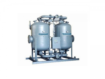
Externally heated air dryer adds a heater based on CWPE dryer to heat the purge air. It not only benefits the regeneration effect but also decreases regeneration purge loss. 8 hours standard cycle, dryer cycles are controlled by a timer.
We can also supply the option functions as below:
l Digital Dew Point Monitor
l PLC Controller With Connection Port
l Without Failure To Shift Alarm -DF1, -RS485, -MODBUS
l Including Failure To Shift Alarm -DF1, -RS485, -MODBUS
l Dew Point Demand Control
Dew Point Demand Control:
The Dew Point is energy conservation method that can extend the drying cycle without extra purging. During periods of lower moisture loads, the Dew Point Demand system offers, in one compact package, the utmost in flexibility and accuracy sensing the actual dew point at the outlet of the dryer. At the end of the drying cycle, it extends the drying cycle until the preset adjustable dew point set-point is reached. During this extended drying cycle the purge valves are closed and the opposite tower is pressurized and prepared for the drying cycle. The dew point demand option consists of the following: Digital Dew Point Display, Adjustable Set Points, Demand Cycle Light, High Humidity Alarm Light With Dry Contact, 4~20mA Output for Remote Annunciation.
DESICCANT - High strength 1/4" activated alumina.
PREFILTER - A high-efficiency (HC) coalescing filter is factory-mounted on the dryer package. The compressed air is pre filtered prior to entering the dryer's drying vessel to collect any contaminants such as dirt, water or oil drop lets from the upstream compressor. The filter has a 0.01 micron and 0.01 ppm rating.
AFTERFILTER - A particulate, (HT) filter is factory-mounted on the dryer package. The compressed air is filtered downstream from the drying vessel to collect any dusting that may have occurred as a result of the drying process. The filter has a 1.0 micron rating.
FILTER DIFFERENTIAL PRESSURE INDICATORS - These are included on pre- and afterfilters to monitor the condition of filter elements.
* For maximum energy efficiency it is recommended to change prefilter and afterfilter elements every year or when they indicate restricted flow.
DRYING VESSELS - Of welded steel construction, all HL models are GB or ASME code stamped. Removable stainless steel screens are provided in the inlet and outlet nozzles of each desiccant tower to prevent carry-over of desiccant. Accessible fill and drain ports.
TOWER PRESSURE GAUGES - 2-1/2" or 3-1/2" dial, 0-300 psig, brass burdon tube mounted on each vessel for ease of visibility.
PRESSURE RELIEF VALVE - A fire-coded safety valve is located on each desiccant chamber. It is set for 165 psig.
SWITCHING VALVES -
High-performance non lubricated diaphragm valve
Normally open inlet valve
Normally closed exhaust valves
Integrated pilot air circuits.
OUTLET CHECK VALVES -
All models use a high performance, steel bodied check valve with aluminum internals and a silicon seat.
CONTROLS - A NEMA 4 Microprocessor Controller with integrated keypad interface is standard. Includes a dryer schematic with visual indications of: dryer on, dryer alarm, left/right tower drying and left/right tower regeneration.
ELECTRICAL ENCLOSURE - NEMA 4 is the standard enclosure. Constructed in accordance with UL/ULC 508A.
ASSEMBLY - Fully assembled on self-supporting fabricated steel frame.
MANUAL PURGE ADJUSTMENT - A purge adjustment valve is included with a mounted purge pressure gauge.
MUFFLERS - One for each purge air outlet.
PIPING AND FITTINGS -
1" to 6" Schedule 40, SA53 Gr. B ERW carbon steel pipe.
1" to 2" uses threaded 150# black malleable iron fittings.
3" to 6" flanged and welded fittings. ANSI B16.5 Class 150 raised face flanges.
| Model | Flow Capacity M3/min | Conn. | Dimensions LxWxH mm | Weight Kg |
| 1.2 | ZG 1" | 405x360x1188 | 190 | |
| 2.4 | ZG 1" | 405x360x1646 | 300 | |
| 3.8 | DN40 | 405x360x1553 | 390 | |
| 6.5 | DN40 | 773x600x1018 | 550 | |
| 8.5 | DN50 | 862x700x1950 | 620 | |
| 10.7 | DN50 | 962x700x1880 | 910 | |
| 13 | DN50 | 962x700x2090 | 1060 | |
| 16 | DN80 | 1175x800x1908 | 1060 | |
| 23 | DN80 | 1175x600x2208 | 1420 | |
| 27 | DN80 | 1175x700x2020 | 1630 | |
| 33 | DN80 | 1175x700x2110 | 2100 | |
| 45 | DN100 | 1465x700x2393 | 2600 | |
| 55 | DN125 | 1815x800x2473 | 3100 | |
| 65 | DN125 | 1815x800x2673 | 3700 | |
| 85 | DN125 | 2013x900x2870 | 4600 | |
| 100 | DN150 | 2300x1500x2933 | 5200 | |
| 150 | DN200 | 2700x1800x3429 | 7800 | |
| 200 | DN250 | 1900x2000x3529 | 8200 |


")


")


")


