Three-Phase Induction Motor


Introduction
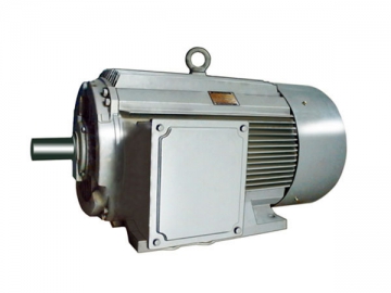
The Y-H Series of the three-phase induction motor is a completely enclosed fan-cooled marine motor of the squirrel-cage type. The motors drive machines on ships such as pumps, blowers, separators, hydraulic engines and other auxiliary equipment. Designed to meet national standard GB755 for the rating and performance of rotating electrical machines and sea-going vessels, the marine induction motors are long lasting even in tougher environments. They also comply with the following standards:
IEC60034 Rotating electrical machines
IEC60068 Basic environmental testing procedures
IEC60072 Dimensions and power ratings for rotating electrical machines
IEC60092 Electrical installation in ships
The motors are also in conformity with part of the specifications of the following Ships Classification Societies.
| LR | Lloyd’s Register of Shipping | GL | Germanischer Lloyd |
| NK | Nippon Kaiji Kyokai | BV | Bureau Veritas |
| ABS | American Bureau of Shipping | KR | Korean Register of Shipping |
| RINA | Register Italiano Navale | RS | Russian Maritime Register of Shipping |
| DNV | Det Norske Veritas |
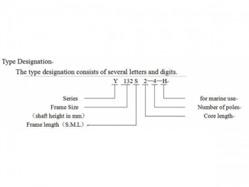
Type Designation
The type designation consists of several letters and numbers.
| Frame Size | No. of Poles | Bearings | ||
| Driving End | Non-Driving End | |||
| B3 , B5, B35 | V1 | |||
| 80 | 2, 4 | 6204-2RS/C3 | 6204-2RS/C3 | |
| 90 | 2, 4, 6 | 6205-2RS/C3 | 6205-2RS/C3 | |
| 100 | 2, 4, 6 | 6206-2RS/C3 | 6206-2RS/C3 | |
| 112 | 2, 4, 6, 8 | 6206-2RS/C3 | 6206-2RS/C3 | |
| 132 | 2, 4, 6, 8 | 6208-2RS/C3 | 6208-2RS/C3 | |
| 160 | 2, 4, 6, 8 | 6309-2RS/C3 | 6309-2RS/C3 | |
| 180 | 2, 4, 6, 8 | 6311/C3 | 6311/C3 | |
| 200 | 2, 4, 6, 8 | 6312/C3 | 6312/C3 | |
| 225 | 2/4, 6, 8 | 6312/C3/6313/C3 | 6312/C3 | |
| 250 | 2/4, 6, 8 | 6313/C3/6314/C3 | 6313/Z2 | |
| 280 | 2/4, 6, 8 | 6314/C3/6317/C3 | 6314/C3 | |
| 315 | 2/4, 6, 8 | 6317/Z2/N319/Z2 | 7317ACJ/7319ACJ | 6317/Z2/6319/Z2 |
| 355 | 2/4, 6, 8 | 6319/Z2/N322/Z2 | 7319ACJ/7322ACJ | 6319/Z2/6322/Z2 |
Power
The power of the motors ranges from 0.55 to 315kW. Table2 shows the relations between frame size and power.
| Frame size | Power: kW | |||
| 2- poles | 4-poles | 6-poles | 8-poles | |
| 80M 1 | 0.75 | 0.55 | - | - |
| 80M2 | 1.1 | 0.75 | ||
| 90S | 1.5 | 1.1 | 0.75 | - |
| 90L | 2.2 | 1.5 | 1.1 | - |
| 100L1 | 3 | 2.2 | 1.5 | - |
| 100L 2 | 3 | |||
| 112M | 4 | 4 | 2.2 | - |
| 132S1 | 5.5 | 5.5 | 3 | 2.2 |
| 132S2 | 7.5 | |||
| 132M 1 | - | 7.5 | 4 | 3 |
| 132M2 | 5.5 | |||
| 160M 1 | 11 | 11 | 7.5 | 4 |
| 160M2 | 15 | 5.5 | ||
| 160L | 18.5 | 15 | 11 | 7.5 |
| 180M | 22 | 18.5 | - | - |
| 180L | - | 22 | 15 | 11 |
| 200L 1 | 30 | 30 | 18.5 | 15 |
| 200L 2 | 37 | 22 | ||
| 225S | - | 37 | - | 18.5 |
| 225M | 45 | 45 | 30 | 22 |
| 250M | 55 | 55 | 37 | 30 |
| 280S | 75 | 75 | 45 | 37 |
| 280M | 90 | 90 | 55 | 45 |
| 315S | 110 | 110 | 75 | 55 |
| 315M | 132 | 132 | 90 | 75 |
| 315L 1 | 160 | 160 | 110 | 90 |
| 315L 2 | 200 | 200 | 132 | 110 |
| 355M 1 | 250 | 250 | 160 | 132 |
| 355M2 | 250 | 250 | 200 | 160 |
| 355L | 315 | 315 | 250 | 200 |
Operating Conditions
Temperature of ambient air 0℃~45℃
Altitude: 0m
Relative humidity: ≤95%
Dew: exists
Salt mist: exists
Oil mist: exists
Fungus: exists
Shock: exists
Vibration: exists
Inclination: ±30°
Swing: ±22.5°
Voltage and Frequency
Rated Voltage: 380V or 440V
Rated Frequency: 50Hz or 60Hz
Connection
3kW or Less: Y
More than 3kW: △
Duty Type
Continuous (S1)
Insulation and Temperature Rise
Insulation: B, F or H
Temp. rise of winding: 75K, 100K or 120K
(resistance method)
Permissible working temp. of bearing 90℃
(thermometer method)
Type of starting
Direct on full-voltage starting for all sizes: reduced voltage starting allowable at no-load or light load.
Driving Method
Pulley, spur or flexible coupling can be used for driving.
Mounting Arrangements
Mounting arrangements available for various frame sizes are shown in table 5.
B3 Horizontal, foot-mounted
B5 Horizontal, flange-mounted
B35 Horizontal, foot and flange mounted
V1 Vertical, flange mounted
Vibration
The limited values of vibration velocity, measured in no-load condition, does not exceed those given in table 3.
| Frame Size | Mounting Arrangements ( IM ) |
| 80~ 225 | B3, B5, B35, V1 |
| 250~ 315 | B3, B35, V1 |
Impregnation and Surface Treatment
The motor windings are impregnated and well treated to be waterproof and resistant to fungus and sea spray, in accordance with specifications for machines in humid climates.
| Frame Size | 80~ 132 | 160~ 280 | 315~ 355 | ||||||
| Mounting Type | Displacement /um | Speed /(mm/s) | Acceleration /(m/s2) | Displacement /um | Speed /(mm/s) | Acceleration /(m/s2) | Displacement /um | Speed /(mm/s) | Acceleration /(m/s2) |
| Free-hanging | 25 | 1.6 | 2.5 | 35 | 2.2 | 3.5 | 45 | 2.8 | 4.4 |
| Rigid Mounting | 21 | 1.3 | 2.0 | 29 | 1.8 | 2.8 | 37 | 2.3 | 3.6 |
| Model | Power kW | Current A | Rotation speed r/min | Weight kg | Model | Power kW | Current A | Rotation speed r/min | Weight kg | ||||
| 380V 50Hz | 440V 60Hz | 380V 50Hz | 440V 60Hz | 380V 50Hz | 440V 60Hz | 380V 50Hz | 440V 60Hz | ||||||
| 0.75 | 1.8 | 1.6 | 2820 | 3460 | 17 | 200 | 361.3 | 319.0 | 1480 | 1790 | 1260 | ||
| 1.1 | 2.6 | 2.2 | 2820 | 3460 | 19 | 250 | 464.5 | 410.2 | 1480 | 1790 | 1600 | ||
| 1.5 | 3.5 | 3.1 | 2840 | 3470 | 23 | 315 | 582.1 | 514.0 | 1480 | 1790 | 1800 | ||
| 2.2 | 4.9 | 4.3 | 2840 | 3470 | 26 | 0.75 | 2.2 | 2.0 | 910 | 1130 | 20 | ||
| 3 | 6.2 | 5.4 | 2880 | 3490 | 33 | 1.1 | 3.2 | 2.9 | 910 | 1130 | 24 | ||
| 4 | 8.2 | 7.2 | 2890 | 3500 | 46 | 1.5 | 4.0 | 3.5 | 940 | 1150 | 33 | ||
| 5.5 | 11.0 | 9.6 | 2900 | 3520 | 78 | 2.2 | 5.8 | 5.2 | 940 | 1150 | 45 | ||
| 7.5 | 14.6 | 12.9 | 2900 | 3520 | 90 | 3 | 7.2 | 6.4 | 960 | 1170 | 66 | ||
| 11 | 21.6 | 18.7 | 2930 | 3540 | 120 | 4 | 9.5 | 8.2 | 960 | 1170 | 80 | ||
| 15 | 28.9 | 25.1 | 2930 | 3540 | 135 | 5.5 | 12.5 | 10.7 | 960 | 1170 | 90 | ||
| 18.5 | 35.7 | 30.3 | 2930 | 3540 | 160 | 7.5 | 17.1 | 14.8 | 970 | 1170 | 100 | ||
| 22 | 42.2 | 36.9 | 2940 | 3550 | 180 | 11 | 25.0 | 21.7 | 970 | 1170 | 125 | ||
| 30 | 57.9 | 50.3 | 2955 | 3560 | 215 | 15 | 33.0 | 29.3 | 970 | 1180 | 195 | ||
| 37 | 69.4 | 60.3 | 2960 | 3565 | 245 | 18.5 | 37.6 | 32.7 | 980 | 1183 | 225 | ||
| 45 | 85.9 | 76.3 | 2969 | 3572 | 330 | 22 | 44.7 | 38.9 | 980 | 1182 | 275 | ||
| 55 | 103.2 | 91.7 | 2970 | 3570 | 400 | 30 | 61.1 | 53.1 | 985 | 1187 | 325 | ||
| 75 | 139.2 | 120.9 | 2970 | 3580 | 535 | 37 | 71.0 | 61.3 | 980 | 1180 | 430 | ||
| 90 | 167.1 | 143.5 | 2970 | 3580 | 550 | 45 | 86.4 | 74.6 | 980 | 1190 | 505 | ||
| 110 | 203.0 | 180.2 | 2970 | 3580 | 980 | 55 | 103.2 | 89.7 | 980 | 1190 | 540 | ||
| 132 | 242.3 | 215.1 | 2970 | 3580 | 1080 | 75 | 141.1 | 124.0 | 980 | 1190 | 990 | ||
| 160 | 292.1 | 259.3 | 2970 | 3580 | 1160 | 90 | 168.6 | 148.1 | 980 | 1190 | 1080 | ||
| 200 | 365.2 | 324.6 | 2970 | 3580 | 1260 | 110 | 205.5 | 180.5 | 980 | 1190 | 1150 | ||
| 250 | 451.4 | 400.6 | 2970 | 3580 | 1600 | 132 | 245.8 | 215.9 | 980 | 1190 | 1210 | ||
| 315 | 565.7 | 502.1 | 2970 | 3580 | 1800 | 160 | 302.0 | 265.3 | 980 | 1190 | 1500 | ||
| 0.55 | 1.5 | 1.4 | 1390 | 1710 | 17 | 200 | 376.7 | 330.9 | 980 | 1190 | 1700 | ||
| 0.75 | 2.1 | 1.8 | 1390 | 1710 | 19 | 250 | 468.9 | 411.9 | 980 | 1190 | 1900 | ||
| 1.1 | 2.7 | 2.4 | 1400 | 1710 | 23 | 2.2 | 5.8 | 5.2 | 710 | 860 | 66 | ||
| 1.5 | 3.6 | 3.2 | 1400 | 1710 | 26 | 3 | 7.6 | 6.8 | 710 | 860 | 80 | ||
| 2.2 | 5.0 | 4.5 | 1420 | 1730 | 36 | 4 | 10.5 | 9.1 | 720 | 870 | 93 | ||
| 3 | 6.8 | 5.9 | 1420 | 1730 | 39 | 5.5 | 13.4 | 11.5 | 720 | 870 | 105 | ||
| 4 | 8.9 | 7.7 | 1440 | 1750 | 47 | 7.5 | 17.7 | 15.5 | 720 | 870 | 130 | ||
| 5.5 | 11.7 | 10.0 | 1440 | 1750 | 78 | 11 | 25.6 | 22.2 | 730 | 880 | 175 | ||
| 7.5 | 15.4 | 13.2 | 1440 | 1750 | 98 | 15 | 33.3 | 29.2 | 729 | 882 | 255 | ||
| 11 | 22.6 | 19.5 | 1460 | 1760 | 123 | 18.5 | 40.3 | 35.6 | 735 | 886 | 300 | ||
| 15 | 30.5 | 26.3 | 1460 | 1760 | 152 | 22 | 47.4 | 41.7 | 734 | 886 | 320 | ||
| 18.5 | 35.9 | 30.8 | 1470 | 1770 | 180 | 30 | 64.7 | 57.1 | 730 | 890 | 420 | ||
| 22 | 42.2 | 36.9 | 1470 | 1770 | 200 | 37 | 79.8 | 68.9 | 740 | 890 | 515 | ||
| 30 | 57.3 | 49.8 | 1476 | 1779 | 260 | 45 | 94.8 | 80.8 | 740 | 890 | 550 | ||
| 37 | 70.2 | 60.3 | 1481 | 1783 | 321 | 55 | 113.5 | 98.6 | 740 | 890 | 1000 | ||
| 45 | 84.0 | 73.4 | 1480 | 1783 | 355 | 75 | 152.1 | 132.1 | 740 | 890 | 1100 | ||
| 55 | 103.8 | 88.7 | 1480 | 1780 | 417 | 90 | 179.3 | 155.7 | 740 | 890 | 1160 | ||
| 75 | 139.2 | 120.9 | 1480 | 1790 | 550 | 110 | 218.5 | 189.6 | 740 | 890 | 1230 | ||
| 90 | 164.3 | 141.9 | 1480 | 1790 | 650 | 132 | 264.8 | 229.9 | 740 | 890 | 1500 | ||
| 110 | 200.8 | 177.3 | 1480 | 1790 | 1000 | 160 | 320.3 | 278.1 | 740 | 890 | 1600 | ||
| 132 | 239.7 | 211.6 | 1480 | 1790 | 1100 | 200 | 399.1 | 346.5 | 740 | 890 | 1800 | ||
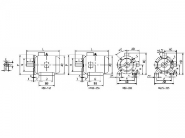
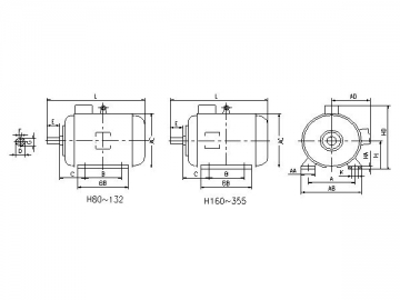
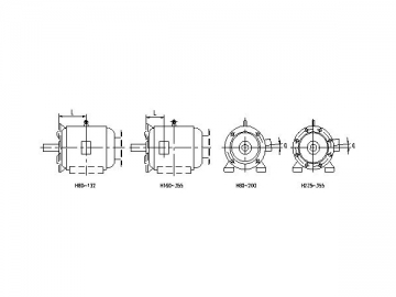
The B3 motor features a frame with feet and an end-shield without flange.
| Frame | Poles | Mounting Dimensions | Overall Dimensions | |||||||||||||||
| A | B | C | D | E | F | G | H | K | AA | BB | HA | AB | AC | AD | HD | L | ||
| 80 | 2,4 | 125 | 100 | 50 | 19 | 40 | 6 | 15.5 | 80 | 10 | 34 | 130 | 10 | 165 | 175 | 160 | 240 | 295 |
| 90S | 2.4,6 | 140 | 100 | 56 | 24 | 50 | 8 | 20 | 90 | 36 | 140 | 12 | 180 | 195 | 175 | 270 | 320 | |
| 90L | 125 | 165 | 360 | |||||||||||||||
| 100L | 160 | 140 | 63 | 28 | 60 | 24 | 100 | 12 | 40 | 176 | 14 | 205 | 215 | 185 | 290 | 385 | ||
| 112M | 190 | 70 | 112 | 45 | 180 | 15 | 245 | 240 | 195 | 320 | 405 | |||||||
| 132S | 2,4,6,8 | 216 | 89 | 38 | 80 | 10 | 33 | 132 | 55 | 186 | 18 | 280 | 275 | 245 | 365 | 480 | ||
| 132M | 178 | 224 | 520 | |||||||||||||||
| 160M | 254 | 210 | 108 | 42 | 110 | 12 | 37 | 160 | 15 | 65 | 260 | 20 | 330 | 330 | 270 | 450 | 605 | |
| 160L | 254 | 304 | 650 | |||||||||||||||
| 180M | 279 | 241 | 121 | 48 | 14 | 42.5 | 180 | 70 | 311 | 22 | 355 | 380 | 290 | 480 | 670 | |||
| 180L | 279 | 349 | 710 | |||||||||||||||
| 200L | 318 | 305 | 133 | 55 | 16 | 49 | 200 | 19 | 70 | 369 | 24 | 395 | 420 | 355 | 550 | 780 | ||
| 225S | 4,8 | 356 | 286 | 149 | 60 | 140 | 18 | 53 | 225 | 75 | 368 | 28 | 435 | 470 | 370 | 585 | 825 | |
| 225M | 2 | 311 | 55 | 110 | 16 | 49 | 393 | 28 | 825 | |||||||||
| 4,6,8 | 60 | 140 | 18 | 53 | 850 | |||||||||||||
| 250M | 2 | 406 | 349 | 168 | 60 | 18 | 53 | 250 | 24 | 80 | 445 | 30 | 490 | 510 | 455 | 660 | 935 | |
| 4,6,8 | 65 | 58 | ||||||||||||||||
| 280S | 2 | 457 | 368 | 190 | 280 | 85 | 485 | 35 | 550 | 580 | 470 | 730 | 1020 | |||||
| 4,6,8 | 75 | 20 | 67.5 | |||||||||||||||
| 280M | 2 | 419 | 65 | 18 | 58 | 536 | 1070 | |||||||||||
| 4,6,8 | 75 | 20 | 67.5 | |||||||||||||||
| 315S | 2 | 508 | 406 | 216 | 65 | 170 | 18 | 58 | 315 | 28 | 120 | 570 | 45 | 744 | 645 | 576 | 875 | 1270 |
| 4,6,8 | 80 | 22 | 71 | |||||||||||||||
| 315M | 2 | 457 | 65 | 18 | 58 | 680 | 1340 | |||||||||||
| 4,6,8 | 80 | 22 | 71 | |||||||||||||||
| 315L | 2 | 508 | 65 | 18 | 58 | 1340 | ||||||||||||
| 4,6,8 | 80 | 22 | 71 | |||||||||||||||
| 355M | 2 | 610 | 560 | 254 | 75 | 20 | 67.5 | 355 | 116 | 750 | 52 | 740 | 750 | 680 | 1045 | 1570 | ||
| 4,6,8 | 95 | 25 | 86 | |||||||||||||||
| 355L | 2 | 630 | 75 | 20 | 67.5 | 1570 | ||||||||||||
| 4,6,8 | 95 | 25 | 86 | |||||||||||||||
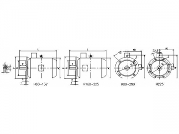
The B35 motor features a frame with feet and an end-shield with flange (with through holes).
| Frame | Poles | Mounting Dimensions | Overall Dimensions | |||||||||||||||||||||
| A | B | C | D | E | F | G | H | K | M | N | P | R | S | T | AA | BB | HA | AB | AC | AD | HD | L | ||
| 80 | 2,4 | 125 | 100 | 50 | 19 | 40 | 6 | 15.5 | 80 | 10 | 165 | 130 | 200 | 0 | 4- φ 12 | 3.5 | 34 | 130 | 10 | 165 | 175 | 160 | 240 | 295 |
| 90S | 2,4,6 | 140 | 56 | 24 | 50 | 8 | 20 | 90 | 36 | 140 | 12 | 180 | 195 | 175 | 270 | 320 | ||||||||
| 90L | 125 | 165 | 360 | |||||||||||||||||||||
| 100L | 160 | 140 | 63 | 28 | 60 | 24 | 100 | 12 | 215 | 180 | 250 | 0 | 4- φ 15 | 4 | 40 | 176 | 14 | 205 | 215 | 185 | 290 | 385 | ||
| 112M | 190 | 70 | 112 | 45 | 180 | 15 | 245 | 240 | 195 | 320 | 405 | |||||||||||||
| 132S | 2,4,6 ,8 | 216 | 89 | 38 | 80 | 10 | 33 | 132 | 265 | 230 | 300 | 55 | 186 | 18 | 280 | 275 | 245 | 365 | 480 | |||||
| 132M | 178 | 224 | 520 | |||||||||||||||||||||
| 160M | 254 | 210 | 108 | 42 | 110 | 12 | 37 | 160 | 15 | 300 | 250 | 350 | 0 | 4- φ 19 | 5 | 65 | 260 | 20 | 330 | 330 | 270 | 450 | 605 | |
| 160L | 254 | 304 | 650 | |||||||||||||||||||||
| 180M | 279 | 241 | 121 | 48 | 14 | 42.5 | 180 | 70 | 311 | 22 | 355 | 380 | 290 | 480 | 670 | |||||||||
| 180L | 279 | 349 | 710 | |||||||||||||||||||||
| 200L | 318 | 305 | 133 | 55 | 16 | 49 | 200 | 19 | 350 | 300 | 400 | 70 | 369 | 24 | 395 | 420 | 355 | 550 | 780 | |||||
| 225S | 4 ,8 | 356 | 286 | 149 | 60 | 140 | 18 | 53 | 225 | 400 | 350 | 450 | 0 | 8- φ 19 | 75 | 368 | 28 | 435 | 470 | 370 | 585 | 825 | ||
| 225M | 2 | 311 | 55 | 110 | 16 | 49 | 393 | 825 | ||||||||||||||||
| 4,6 ,8 | 60 | 140 | 18 | 53 | 850 | |||||||||||||||||||
| 250M | 2 | 406 | 349 | 168 | 250 | 24 | 500 | 450 | 550 | 80 | 445 | 30 | 490 | 510 | 455 | 660 | 935 | |||||||
| 4,6 ,8 | 65 | 58 | ||||||||||||||||||||||
| 280S | 2 | 457 | 368 | 190 | 280 | 85 | 485 | 35 | 550 | 580 | 470 | 730 | 1020 | |||||||||||
| 4,6 ,8 | 75 | 20 | 67.5 | |||||||||||||||||||||
| 280M | 2 | 419 | 65 | 18 | 58 | 536 | 1070 | |||||||||||||||||
| 4,6 ,8 | 75 | 20 | 67.5 | |||||||||||||||||||||
| 315S | 2 | 508 | 406 | 216 | 65 | 170 | 18 | 58 | 315 | 28 | 600 | 550 | 660 | 8- φ 24 | 6 | 120 | 570 | 45 | 744 | 645 | 576 | 875 | 1270 | |
| 4,6 ,8 | 80 | 22 | 71 | |||||||||||||||||||||
| 315M | 2 | 457 | 65 | 18 | 58 | 680 | 1340 | |||||||||||||||||
| 4,6 ,8 | 80 | 22 | 71 | |||||||||||||||||||||
| 315L | 2 | 508 | 65 | 18 | 58 | 1340 | ||||||||||||||||||
| 4,6 ,8,10 | 80 | 22 | 71 | |||||||||||||||||||||
| 355M | 2 | 610 | 560 | 254 | 75 | 20 | 67.5 | 355 | 740 | 680 | 800 | 116 | 750 | 52 | 740 | 750 | 680 | 1045 | 1570 | |||||
| 4,6 ,8 | 95 | 25 | 86 | |||||||||||||||||||||
| 355L | 2 | 630 | 75 | 20 | 67.5 | 1570 | ||||||||||||||||||
| 4,6 ,8 | 95 | 25 | 86 | |||||||||||||||||||||
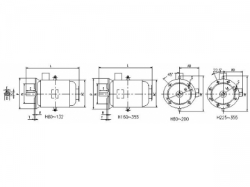
The V1 motor is vertically mounted and features a frame without feet, an end-shield with flange, and a shaft extension downward
| Frame | Poles | Mounting Dimensions | Overall Dimensions | ||||||||||||
| D | E | F | G | M | N | P | R | S | T | AC | AD | HF | L | ||
| 80 | 2,4 | 19 | 40 | 6 | 15.5 | 165 | 130 | 200 | 0 | 4- φ 12 | 3.5 | 175 | 160 | 270 | 335 |
| 90S | 2,4,6 | 24 | 50 | 8 | 20 | 195 | 175 | 365 | |||||||
| 90L | 400 | ||||||||||||||
| 100L | 28 | 60 | 24 | 215 | 180 | 250 | 4- φ 15 | 4 | 215 | 185 | 300 | 410 | |||
| 112M | 240 | 195 | 320 | 450 | |||||||||||
| 132S | 2,4,6 ,8 | 38 | 80 | 10 | 33 | 265 | 230 | 300 | 275 | 245 | 380 | 535 | |||
| 132M | 575 | ||||||||||||||
| 160M | 42 | 110 | 12 | 37 | 300 | 250 | 350 | 0 | 4- φ 19 | 5 | 330 | 270 | 450 | 660 | |
| 160L | 705 | ||||||||||||||
| 180M | 48 | 14 | 42.5 | 300 | 250 | 350 | 0 | 380 | 290 | 500 | 730 | ||||
| 180L | 765 | ||||||||||||||
| 200L | 55 | 16 | 49 | 350 | 300 | 400 | 0 | 420 | 355 | 550 | 840 | ||||
| 225S | 4,8 | 60 | 140 | 18 | 53 | 400 | 350 | 450 | 0 | 8- φ 19 | 470 | 370 | 610 | 890 | |
| 225M | 2 | 55 | 110 | 16 | 49 | 865 | |||||||||
| 4,6,8 | 60 | 140 | 18 | 53 | 915 | ||||||||||
| 250M | 2 | 500 | 450 | 550 | 0 | 510 | 455 | 650 | 995 | ||||||
| 4,6,8 | 65 | 58 | |||||||||||||
| 280S | 2 | 580 | 470 | 720 | 1090 | ||||||||||
| 4,6 | 75 | 20 | 67.5 | ||||||||||||
| 280M | 2 | 65 | 18 | 58 | 1140 | ||||||||||
| 4,6,8 | 75 | 20 | 67.5 | ||||||||||||
| 315S | 2 | 65 | 170 | 18 | 58 | 600 | 550 | 660 | 8- φ 24 | 6 | 645 | 576 | 900 | 1390 | |
| 4,6 ,8 | 80 | 22 | 71 | ||||||||||||
| 315M | 2 | 65 | 18 | 58 | 1490 | ||||||||||
| 4,6 ,8 | 80 | 22 | 71 | ||||||||||||
| 315L | 2 | 65 | 18 | 58 | 1490 | ||||||||||
| 4,6 ,8 | 80 | 22 | 71 | ||||||||||||
| 355M | 2 | 75 | 20 | 67.5 | 740 | 680 | 800 | 750 | 680 | 1035 | 1675 | ||||
| 4,6 ,8 | 95 | 25 | 86 | ||||||||||||
| 355L | 2 | 75 | 20 | 67.5 | 1675 | ||||||||||
| 4,6 ,8 | 95 | 25 | 86 | ||||||||||||
The B5 motor features a frame without feet and an end-shield with flange (with through holes).
| Frame | Poles | Mounting Dimensions | Overall Dimensions | ||||||||||||
| D | E | F | G | M | N | P | R | S | T | AC | AD | HF | L | ||
| 80M | 2,4 | 19 | 40 | 6 | 15.5 | 165 | 130 | 200 | 0 | 4- φ 12 | 3.5 | 175 | 160 | 235 | 295 |
| 90S | 2,4,6 | 24 | 50 | 8 | 20 | 195 | 175 | 320 | |||||||
| 90L | 360 | ||||||||||||||
| 100L | 28 | 60 | 24 | 215 | 180 | 250 | 4- φ 15 | 4 | 215 | 185 | 275 | 385 | |||
| 112M | 240 | 195 | 285 | 405 | |||||||||||
| 132S | 2,4,6 ,8 | 38 | 80 | 10 | 33 | 265 | 230 | 300 | 275 | 245 | 340 | 480 | |||
| 132M | 520 | ||||||||||||||
| 160M | 42 | 110 | 12 | 37 | 300 | 250 | 350 | 0 | 4- φ 19 | 5 | 330 | 270 | 400 | 605 | |
| 160L | 650 | ||||||||||||||
| 180M | 48 | 14 | 42.5 | 300 | 250 | 350 | 0 | 380 | 290 | 500 | 670 | ||||
| 180L | 710 | ||||||||||||||
| 200L | 55 | 16 | 49 | 350 | 300 | 400 | 0 | 420 | 355 | 550 | 780 | ||||
| 225S | 4,8 | 60 | 140 | 18 | 53 | 400 | 350 | 450 | 0 | 8- φ 19 | 470 | 370 | 610 | 825 | |
| 225M | 2 | 55 | 110 | 16 | 49 | 825 | |||||||||
| 4,6,8 | 60 | 140 | 18 | 53 | 850 | ||||||||||
The terminal box is installed on the right side of the motor (when facing the driving end of the motor).
| Frame | L mm | α | Remark | Frame | L mm | α | Remark |
| Y80-H | 100 | 7.5 ° | Y180-H | 161 | 5 ° | ||
| Y90S-H | 106 | 7.5 ° | Y200L-H | 186 | 0 ° | ||
| Y90L-H | 118.5 | 7.5 ° | Y225-H | 189 | 0 ° | ||
| Y100L-H | 133 | 7.5 ° | Y250-H | 207 | 0 ° | ||
| Y112M-H | 140 | 5 ° | Y280-H | 215.5 | 0 ° | ||
| Y132S-H | 159 | 4 ° | Y315-H | 257 | 0 ° | ||
| Y132M-H | 178 | 4 ° | Y355-H | 281 | 0 ° | ||
| Y160-H | 146 | 4 ° |
")
, JBZ2-H Series")
")
")


")


