Filter Reactor
Uses
Harmonics are unwanted energy losses generated by non-linear loads in a power system. A harmonic filter, typically enclosed in a metal cabinet, is often used to remove harmonics from the circuit. This filter consists of a filter reactor connected in series with a capacitor bank, forming a complete filter circuit tuned to a specific resonant frequency in order to absorb harmonic currents at the corresponding harmonic frequency.
Standards
1.GB/T 10229-1988
2.IEC 289: 1987
As we mentioned above, harmonics are mainly caused by non-linear loads and components. These elements include the rectifier, variable speed drive, and transformer, which are typically called the source of harmonics. Harmonics have a detrimental effect on the power system as well as the electric loads connected to the system. That is why we should use a filter reactor, which is then connected to the capacitor bank, to eliminate harmonics and improve the power factor of a system.
Operating Conditions
1. Altitude: No more than 2000m
2. Ambient temperature: -25°C~ 45°C
3. Relative humidity: below 90%
4. Workplace should be free of flammables, explosives and hazardous gases.
5. The filter cabinet should be well ventilated.
Key Performance Parameters
1. Used in 400V, 660V power systems
2. Rated dielectric strength: 3kV/min
3. Temperature limits: iron core, no more than 85K; coil, no more than 95K
4. Noise level: no more than 45dB
5. Reactance difference between any two phases: no more than ±3%
6. Insulation level: Class h, at 180°C
7. Quality factor: 40
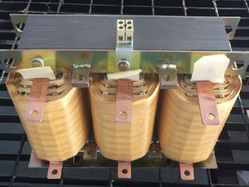
The filter reactor does not have definite specs to follow, as each should be custom designed. Here we take a three-phase filter reactor as an example. But note that data below are for reference only.
| Model No. | Reactor Inductance ( μH ) | Capacitor Capacitance ( μF ) | Ordinal Number of Harmonic | Rated Current (A) | Dimensions L×W×H (mm) | Installation (mm) |
| -0.4-25/1986 | 1986 | 231 | 5th | 25 | 225×155×200 | 175×95 |
| -0.4-31/1582 | 1582 | 290 | 5th | 31 | 225×160×200 | 175×95 |
| -0.4-37/1318 | 1318 | 346 | 5th | 37 | 250×170×200 | 200×100 |
| -0.4-50/981 | 981 | 462 | 5th | 50 | 265×190×215 | 215×120 |
| -0.4-62/790 | 790 | 579 | 5th | 62 | 280×205×230 | 230×125 |
| -0.4-74/659 | 659 | 692 | 5th | 74 | 280×210×260 | 230×125 |
| -0.4-93/527 | 527 | 861 | 5th | 93 | 285×200×290 | 215×125 |
| -0.4-112/438 | 438 | 1027 | 5th | 112 | 265×200×355 | 215×125 |
| -0.4-124/396 | 396 | 1137 | 5th | 124 | 265×205×280 | 215×125 |
| -0.4-149/329 | 329 | 1385 | 5th | 149 | 280×220×420 | 230×145 |
| -0.4-186/264 | 264 | 1770 | 5th | 186 | 330×230×420 | 290×145 |
| -0.4-248/198 | 198 | 2275 | 5th | 248 | 325×285×480 | 265×175 |
| -0.4-310/58 | 158 | 2895 | 5th | 310 | 350×330×520 | 290×205 |
| -0.4-372/132 | 132 | 3539 | 5th | 372 | 420×350×545 | 360×245 |
| Model No. | Reactor Inductance ( μH ) | Capacitor Capacitance ( μF ) | Ordinal Number of Harmonic | Rated Current (A) | Dimensions L×W×H (mm) | Installation (mm) |
| -0.424/1009 | 1009 | 231 | 7th | 24 | 205×155×155 | 155×95 |
| -0.4-30/810 | 810 | 290 | 7th | 30 | 205×165×155 | 155×95 |
| -0.4-36/676 | 676 | 346 | 7th | 36 | 235×165×160 | 185×95 |
| -0.4-48/506 | 506 | 462 | 7th | 48 | 250×175×175 | 200×100 |
| -0.4-61/402 | 402 | 579 | 7th | 61 | 250×185×195 | 200×100 |
| -0.4-73/337 | 337 | 692 | 7th | 73 | 265×200×195 | 215×110 |
| -0.4-91/269 | 269 | 861 | 7th | 91 | 235×158×240 | 185×110 |
| -0.4-109/225 | 225 | 1027 | 7th | 109 | 235×185×260 | 185×110 |
| 0.4-121/191 | 191 | 1137 | 7th | 121 | 238×190×280 | 185×110 |
| -0.4-146/159 | 159 | 1385 | 7th | 146 | 250×205×315 | 200×125 |
| -0.4-182/127 | 127 | 1770 | 7th | 182 | 250×210×340 | 200×125 |
Please do let us know if your filter reactor is to be used in a medium-frequency induction heating furnace due to its special nature.
5% taps can be added along the transformer winding (to fine-tune the filter for different resonance frequencies). If need those winding taps, be sure to mention it upon asking a price quote. Taps are metal loops you would see on the transformer winding. 5% tap means the tap adjusts turns ratio in 5% increment.
This filter reactor is mainly used in an active harmonic filter.


")


")


