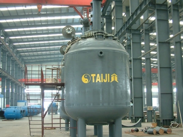
Glass-Lined Reactor, F Type


Main Features
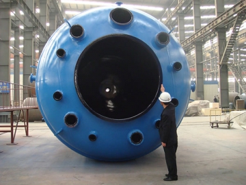
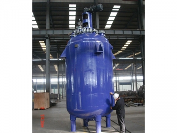
1.The F type glass lined reactor comes with a one-piece design that the cover and body can not be separated. Due to that, a manhole has to be designed on the head of the reactor to make it easy for operators to enter the reactor to carry out maintenance and parts replacement.
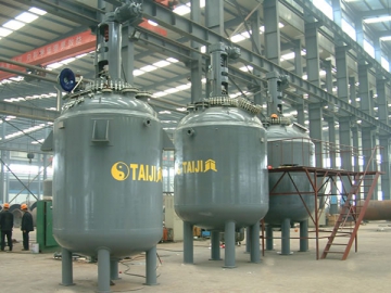
2. It is a large capacity industrial process reactor, suitable for large scale production environment.
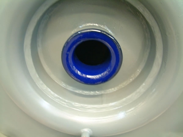
3. Similar to the K-type reactor, this type of chemical reactor is manufactured using TJ09 high end enamel and skilled enameling process. This enables the glass lining to be remarkably corrosion resistant, impact resistant and temperature variation resistant, combined with less prone to fracture and high durability.
4. Taiji is able to design and manufacture non standard glass lined reactor to user's requirements.
5. Our F type glass lined steel reactor comes in complete specifications, including F1500L, F2000L, F3000L, F4000L, F5000L, F6300L, F8000L, F10000L, F12500L, F16000L, F20000L, F30000L, F50000L, etc.
- Parameter Test
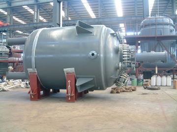
- Finished Product Inspection
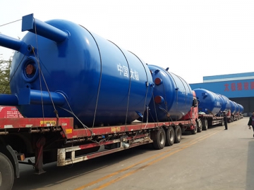
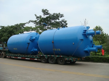
- Transportation
- Transportation
| Internal Vessel | Jacket | |
| Design Pressure (MPa) | 0.4/0.6/1.0 | 0.6/1.0 |
| Design Temperature ( ℃ ) | -19 ℃ /200℃ | -19 ℃ /200℃ |
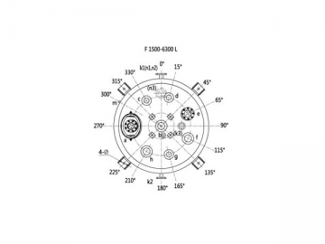
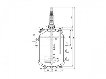
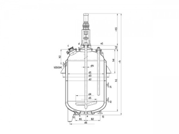
| Symbol | Usage |
| a | Manhole |
| b | Agitator Hole |
| c | Thermowell |
| d, f, g, h | Spare |
| e | Sightglass |
| j | Medium Outlet |
| k1, k2, k3 | In/Outlet |
| n1, n2, n3 | Spray Nozzle |
| m | Vent Hole |
| Unit: mm | |||||||
| Specifications | |||||||
| Nominal Capacity (L) | 1500 | 2000 | 3000 | 4000 | 5000 | 6300 | |
| Total Capacity (L) | 2020 | 2470 | 3860 | 4795 | 6040 | 6900 | |
| Calculated Capacity(Notes 1) (L) | 1990 | 2440 | 3830 | 4795 | 6016 | 6872 | |
| Jacket Capacity (L) | 301 | 390 | 495 | 805 | 898 | 1015 | |
| Heat Exchange Area ( m2 ) | 5.92 | 7.31 | 9.98 | 12.44 | 14.06 | 16.36 | |
| Reference Weight (kg) | 2120 | 2380 | 3360 | 3905 | 4720 | 5200 | |
| Main Dimensions | d1 | 1300 | 1300 | 1600 | 1600 | 1750 | 1750 |
| d2 | 1450 | 1450 | 1750 | 1750 | 1900 | 1900 | |
| d3(Notes 2) | 1622 | 1622 | 1964 | 1964 | 2152 | 2152 | |
| d4 | 680 | 680 | 720 | 720 | 720 | 720 | |
| d5 | 700 | 700 | 800 | 800 | 850 | 850 | |
| h1 | 1801 | 2136 | 2250 | 2730 | 2888 | 3244 | |
| h2 | 190 | 190 | 190 | 190 | 190 | 190 | |
| h3 | 725 | 725 | 700 | 700 | 750 | 750 | |
| h4 | 975 | 975 | 1060 | 1060 | 1200 | 1200 | |
| B1 | 315 | 315 | 315 | 315 | 350 | 350 | |
| B2 | 510 | 510 | 510 | 510 | 510 | 510 | |
| Φ | 30 | 30 | 30 | 30 | 30 | 30 | |
| Nozzle DN | a | 300×400 | 300×400 | 300×400 | 300×400 | 300×400 | 300×400 |
| b | 125 | 125 | 150 | 150 | 150 | 150 | |
| c | 100 | 100 | 100 | 100 | 125 | 125 | |
| d | 100 | 100 | 100 | 100 | 125 | 125 | |
| e | 125 | 125 | 125 | 125 | 125 | 125 | |
| f | 125 | 125 | 125 | 125 | 150 | 150 | |
| g | 100 | 100 | 100 | 100 | 125 | 125 | |
| h | 125 | 125 | 125 | 125 | 150 | 150 | |
| j | 100 | 100 | 125 | 125 | 125 | 125 | |
| Jacket Nozzle DN | k1 | 40 | 40 | 65 | 65 | 65 | 65 |
| k2 | 40 | 40 | 65 | 65 | 65 | 65 | |
| k3 | 40 | 40 | 65 | 65 | 65 | 65 | |
| n1 | 50 | 50 | 65 | 65 | 65 | 65 | |
| n2 | / | / | / | 65 | 65 | 65 | |
| n3 | 50 | 50 | 65 | 65 | 65 | 65 | |
| m | G3/8" | G3/8" | G3/8" | G3/8" | G3/8" | G3/8" | |
| Drive | DN | 80 | 80 | 95 | 95 | 95 | 95 |
| h5 | 1320 | 1320 | 1360 | 1360 | 1360 | 1530 | |
| Notes 1: Calculated Capacity: Volume under highneck flange. | |||||||
| Notes 2: Types of support depend on users; if there is no special request, lugs would be normally applied. | |||||||
| Inner Vessel | Jacket | |
| Design Pressure (MPa) | 0.4/0.6/1.0 | 0.6/1.0 |
| Design Temperature ( ℃ ) | -19 ℃ /200℃ | -19 ℃ /200℃ |
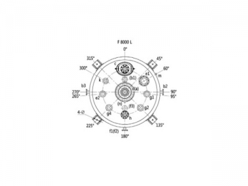
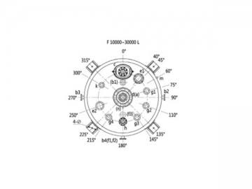
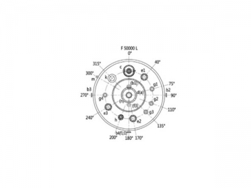
| Symbol | Usage |
| a | Medium Outlet |
| b1,b2,b3,b4 | In/Outlet |
| c | Manhole |
| d | Agitator Hole |
| e1 | Thermowell |
| e2, g1, g2, g3, g4, k | Spare |
| h | Sightglass |
| m | Vent Hole |
| n | Clean Hole |
- F50000L Nozzle Design (Plan View)
- F8000L Nozzle Design (Plan View)
- F10000L~F30000L Nozzle Design (Plan View)
| Unit: mm | ||||||||
| Specifications | ||||||||
| Nominal Capacity (L) | 8000 | 10000 | 12500 | 16000 | 20000 | 30000 | 50000 | |
| Total Capacity (L) | 9105 | 11719 | 13696 | 17491 | 21835 | 33645 | 56444 | |
| Calculated Capacity(Notes 1) (L) | 9060 | 11674 | 13651 | 17446 | 21790 | 33500 | 55514 | |
| Jacket Capacity (L) | 1666 | 1940 | 2243 | 2551 | 2870 | 3700 | 4520 | |
| Heat Exchange Area ( ㎡ ) | 18.38 | 21.35 | 24.89 | 29.48 | 34.04 | 45 | 34.04 | |
| Reference Weight (kg) | 6959 | 7911 | 9342 | 11222 | 13530 | 19270 | 34590 | |
| Main Dimension | d1 | 2000 | 2200 | 2200 | 2400 | 2600 | 3000 | 3800 |
| d2 | 2200 | 2400 | 2400 | 2600 | 2800 | 3200 | 4000 | |
| d3(Notes 2) | 2452 | 2703 | 2703 | 2908 | 3179 | / | / | |
| h1 | 3310 | 3533 | 4053 | 4346 | 4641 | 5340 | 5611 | |
| h2 | 210 | 210 | 210 | 210 | 210 | 260 | 647 | |
| h3 | 850 | 900 | 900 | 950 | 1000 | 1150 | 1340 | |
| h4 | 1200 | 1300 | 1300 | 1400 | 1550 | / | / | |
| h | 5400 | 5600 | 6530 | 7010 | 7475 | 8835 | 10425 | |
| B1 | 400 | 470 | 470 | 470 | 470 | 470 | 470 | |
| B2 | 510 | 550 | 550 | 550 | 550 | 550 | 550 | |
| Φ | 30 | 36 | 36 | 36 | 36 | / | / | |
| Nozzle DN | a | 125 | 150 | 150 | 150 | 150 | 150 | 150 |
| c | 300×400 | 300×400 | 300×400 | 450 | 450 | 450 | 450 | |
| d | 200 | 200 | 200 | 200 | 250 | 250 | 250 | |
| e1 | 200 | 200 | 200 | 200 | 200 | 200 | 200 | |
| e2 | 150 | 200 | 200 | 200 | 200 | 200 | 200 | |
| e3 | / | / | / | / | / | / | 200 | |
| g1 | 150 | 150 | 150 | 150 | 150 | 150 | 150 | |
| g2 | 150 | 150 | 150 | 150 | 150 | 150 | 150 | |
| g3 | / | 150 | 150 | 150 | 150 | 150 | 150 | |
| g4 | 150 | 150 | 150 | 150 | 150 | 150 | 150 | |
| h | 125 | 125 | 125 | 125 | 125 | 125 | 125 | |
| k | 125 | 125 | 125 | 125 | 125 | 125 | 125 | |
| Jacket Nozzle DN | b1 | 65 | 80 | 80 | 100 | 100 | 100 | 125 |
| b2 | 65 | 80 | 80 | 100 | 100 | 100 | 125 | |
| b3 | 65 | 80 | 80 | 100 | 100 | 100 | 125 | |
| b4 | / | 80 | 80 | 100 | 100 | 100 | 100 | |
| f1 | 65 | 80 | 80 | 100 | 100 | 100 | 100 | |
| f2 | 65 | 80 | 80 | 100 | 100 | 100 | 100 | |
| f3 | 65 | 80 | 80 | 100 | 100 | 100 | 100 | |
| m | G3/4" | G3/4" | G3/4" | G3/4" | G3/4" | G3/4" | G3/4" | |
| n | G1/2" | G1/2" | G1/2" | G1/2" | G1/2" | G1/2" | G1/2" | |
| Drive | DN | 110 | 110 | 110 | 130 | 140 | 160 | 160 |
| h5 | 1375 | 1375 | 1375 | 1995 | 2190 | 2420 | 2640 | |
| Notes 1: Calculated Capacity: Volume under highneck flange. | ||||||||
| Notes 2: Support types could be determined by users; if there is no special request, lugs would be normally applied. | ||||||||
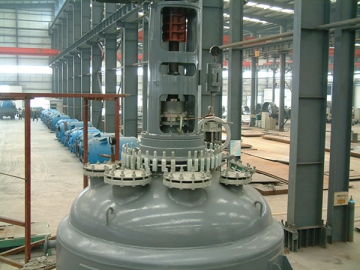
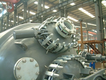
- Upper Structure
- Manhole with Sight Glass
- Bottom Outlet
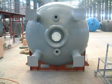
- Bottom View
- Side View
- Front View
- Production Line


")

")


")


