MG1624 Mortise Lever Lock


Request a Quote
This product has been discontinued and removed from our shelves.
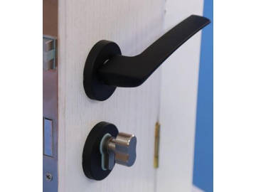
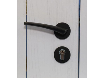
MG1624 mortise lever locks are designed with keys. Doors are locked using the keys, making them safer than other door types. The lock body shells are made of galvanized steel plates and latch bolts are made of POM and zinc alloy, ensuring an excellent muting effect. Levers are made of aluminum alloy and surfaces are treated through electroplating, painting, and polishing, ensuring a better color adhesion, no paint loss, a better corrosion resistance, and a higher durability. Lock colors are customizable.
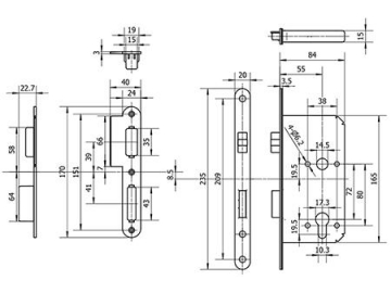
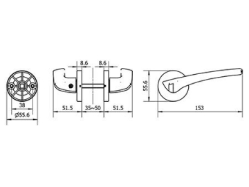
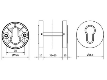
Dimensions
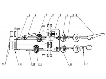
Parts List
| No. | Name | No. | Name |
| 1 | lock body | 9 | Lever fixing screw |
| 2 | Front plate | 10 | Plate fixing screw |
| 3 | Latch Bolt | 11 | Outside cylinder plate |
| 4 | Dead Bolt | 12 | Inside cylinder plate |
| 5 | Outer escutcheon plate | 13 | Cylinder lock |
| 6 | Inner escutcheon plate | 14 | Cylinder fitting screw |
| 7 | Outer Lever Handle | 15 | striking plate |
| 8 | Inner Lever Handle | 16 | Wrought box |
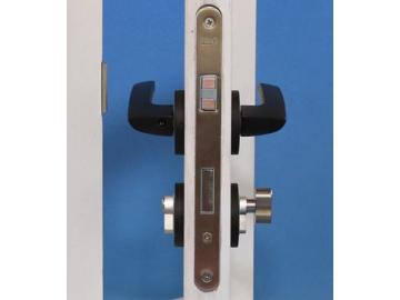
Installation Instructions
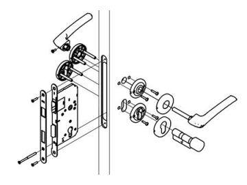
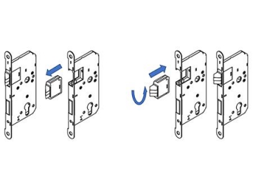
- Determine the door opening direction. Place the lock body into the set hole, ensuring the latch bolt is on the upper side, and the dead bolt on the lower side. Ensure the latch bolt’s inclined surface is facing the door closing direction. If it isn’t, pull the dead bolt out of the lock body, insert 180°, then insert it back into the lock body. Install the front armor and tighten the screws.
- Install escutcheon plates and tighten screws. Connect the outer lever equipped with a square bar through the lock body’s square hole using the Inner Lever Handle, then tighten the screws.
- Install the cylinder thumb turn plates and tighten screws. Send the lock cylinder from the hole on the inside plate through the lock body and outer plate, then attach the cylinder to the front armor with cylindrical screws.
- Install the striking plate on the door frame’s corresponding position. After determining the door opening direction, install the wrought iron striking plate. Ensure the latch both and dead bolt move freely in and out. Notice: 8.5mm center line deviation on striking plate and lock body.
- Test after installation: Rotate the lever handles and press the latch bolt by hand in the inclined surface direction. The latch bolt should freely turn over and smoothly be pressed into and removed from the lock body. When pressing the latch bolt without the rotating lever handle, the latch bolt will not turn over. If the latch bolt operates smoothly, installation is complete. If not, reset all components.
Related products


Send Message
Other Products


Most Recent

")


More


")

")

Other Products


Videos


