Cross Cylindrical Roller Slewing Bearings

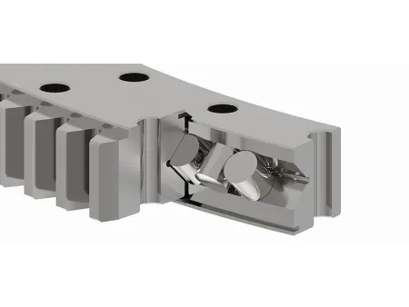


Cross cylindrical roller slewing bearings are designed for applications that demand high rigidity and precise load handling. In this design, cylindrical rollers are arranged crosswise, allowing them to make line contact with the raceways. This structure provides excellent stability and the ability to manage multiple loads simultaneously, including axial loads, radial loads, and overturning moments. Due to this configuration, the bearing is highly capable of absorbing impact loads and maintaining a stable rotation, even under challenging conditions. While these bearings offer a high dynamic load capacity, the cross arrangement also results in greater frictional resistance during operation, which can limit the rotational speed. Additionally, the small internal clearance makes the bearing sensitive to deformations in the mounting structure, requiring careful installation.
These bearings are generally manufactured using 42CrMo4 steel, with the raceways hardened through an induction process to ensure durability. However, depending on the application, alternative materials can be selected to meet specific operational needs.
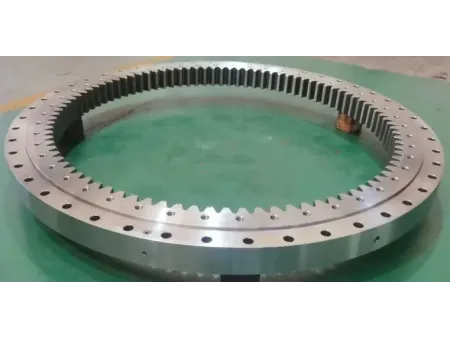
LYXQL can produce cross cylindrical roller slewing bearings with an outer diameter of up to 20 meters. The gear module size can go up to 45mm.
Cross cylindrical roller slewing bearings are available in three distinct configurations to accommodate various application needs: external gear, internal gear, and gearless designs. Each configuration consists of essential components such as inner and outer rings, cylindrical rollers, spacers (as needed), and seals. Depending on the specific operational environment, additional dust-proofing features, like dust covers or ash shields, can be added to enhance the bearing's durability and performance.
- 1: outer ring
- 2: inner ring
- 3: steel ball
- 4: seal
This design features gear teeth on the outer ring, making it suitable for applications where the gear mesh occurs externally. Due to the external positioning of the gear, this configuration generally requires more installation space compared to an internal gear design.
The following specifications are from a previous version of our catalog. If you require the latest data or custom configurations, please don’t hesitate to contact us directly.
| Boundary dimensions | Bolt hole diameter | Structure dimensions | Gear parameters | Basic load ratings | Mass | ||||||||||||||||
| D | d | H | D1 | D2 | n1 | n2 | ⌀1 | ⌀2 | D3 | d1 | H1 | h | n3 | ⌀3 | m | Da | Z | b | x | Coa | kg |
| mm | mm | mm | mm | mm | mm | mm | 104N | ||||||||||||||
| 1056 | 885 | 83 | 1032 | 925 | 16 | 16 | M16 | 17.5 | 986 | 988 | 75 | 12.5 | -- | -- | 8 | 1096 | 135 | 62.5 | 0 | 176 | 172 |
| 1056 | 885 | 83 | 1032 | 925 | 16 | 16 | M16 | 17.5 | 986 | 988 | 75 | 12.5 | -- | -- | 8 | 1096 | 135 | 62.5 | 0 | 176 | 172 |
| 1056 | 885 | 83 | 1032 | 925 | 16 | 16 | M16 | 17.5 | 986 | 988 | 75 | 12.5 | 3 | M10X1 | 8 | 1096 | 135 | 62.5 | 0 | 176 | 172 |
| 1150 | 885 | 115 | 1115 | 935 | 16 | 16 | 18 | 18 | 1023 | 1027 | 100 | 15 | 4 | M8X1 | 5 | 1180 | 234 | 80 | 0 | 292 | 330 |
| 1415 | 1100 | 115 | 1345 | 1160 | 24 | 18 | 21 | 21 | 1253 | 1255 | 100 | 15 | 4 | M12X1.25 | 6 | 1452 | 240 | 84 | 0 | 270 | 497 |
| 1400 | 1100 | 140 | 1352 | 1160 | 26 | 26 | 24 | 26 | 1260 | 1264 | 126 | 21 | 4 | M10X1 | 14 | 1477.28 | 104 | 90 | -0.24 | 430 | 642 |
| 1400 | 1100 | 145 | 1352 | 1160 | 26 | 26 | 24 | 26 | 1260 | 1264 | 131 | 26 | 4 | M10X1 | 14 | 1477.28 | 104 | 90 | -0.24 | 430 | 644 |
| 1548 | 1250 | 148 | 1512 | 1297 | 16 | 16 | 25 | 25 | 1403 | 1407 | 122 | 20 | 4 | M10X1 | 12 | 1608 | 132 | 100 | 0 | 539 | 661 |
| 1595 | 1278 | 120 | 1535 | 1335 | 36 | 36 | 26 | 26 | 1428 | 1432 | 105 | 15 | 4 | M10X1 | 12 | 1655.46 | 134 | 90 | 1.15 | 485 | 597 |
| 1705 | 1300 | 165 | 1644 | 1360 | 24 | 24 | 32 | 32 | 1504 | 1508 | 134 | 31 | 4 | M10X1 | 14 | 1783.6 | 126 | 85 | -0.3 | 578 | 1023 |
| 1715 | 1400 | 110 | 1660 | 1460 | 42 | 42 | 26 | 26 | 1558 | 1562 | 95 | 17 | 4 | M12X1.25 | 12 | 1780.8 | 147 | 78 | -0.3 | 597 | 579 |
| 1715 | 1400 | 110 | 1660 | 1460 | 42 | 42 | 26 | 26 | 1558 | 1562 | 95 | 17 | 4 | M12X1.25 | 12 | 1780.8 | 147 | 78 | -0.3 | 597 | 579 |
| 1715 | 1400 | 110 | 1660 | 1460 | 42 | 42 | 26 | 26 | 1558 | 1562 | 95 | 15 | 4 | M12X1.25 | 12 | 1780.8 | 147 | 78 | -0.3 | 597 | 579 |
| 1800 | 1460 | 125 | 1735 | 1525 | 32 | 36 | 26 | 26 | 1633 | 1637 | 110 | 10 | 4 | M10X1 | 14 | 1881.6 | 133 | 95 | -0.3 | 627 | 828 |
| -- | 1460 | 125 | 1735 | 1525 | 32 | 36 | 26 | 26 | 1633 | 1637 | 110 | 10 | 4 | M10X1 | 10 | 1880 | 186 | 115 | 0 | 627 | 845 |
| -- | 1916 | 150 | 2245 | 1980 | 42 | 42 | 34 | 34 | 2113 | 2117 | 130 | 15 | 3 | M10X1 | 18 | 2415.6 | 133 | 135 | -0.4 | 1150 | 1597 |
| 2600 | 2100 | 180 | 2540 | 2200 | 48 | 48 | 32 | 32 | 2368 | 2372 | 158 | 22 | 8 | M10X1 | 18 | 2700 | 148 | 130 | 0 | 1100 | 2395 |
| 2600 | 2100 | 180 | 2540 | 2200 | 48 | 48 | 32 | 32 | 2368 | 2372 | 158 | 22 | 8 | M10X1 | 18 | 2700 | 148 | 130 | 0 | 1100 | 2392 |
| -- | 2460 | 220 | 2930 | 2560 | 30 | 30 | 33 | 34 | 2745 | 2747 | 185 | 20 | 30 | M12X1.25 | 14 | 3108 | 220 | 200 | 0 | 1386 | 4091 |
| -- | 2460 | 220 | 2930 | 2560 | 30 | 30 | 33 | 34 | 2745 | 2747 | 185 | 20 | 30 | M12X1.25 | 14 | 3108 | 220 | 200 | 0 | 1386 | 4091 |
| 3108 | 2460 | 220 | 2930 | 2560 | 30 | 30 | 33 | 34 | 2745 | 2747 | 200 | 35 | 15 | ZG1/4in | 14 | 3108 | 220 | 200 | 0 | 1386 | 4091 |
| 3108 | 2460 | 220 | 2930 | 2560 | 30 | 30 | 33 | 34 | 2745 | 2747 | 200 | 35 | 30 | ZG1/4in | 14 | 3108 | 220 | 200 | 0 | 1386 | 4091 |
| -- | 2500 | 210 | 2990 | 2630 | 36 | 36 | 37 | 37 | 2818 | 2822 | 200 | 10 | 12 | M14X1.5 | 25 | 3250 | 128 | 200 | 0 | 1996 | 4597 |
| 2500 | 260 | 3060 | 2622 | 36 | 36 | 40 | 40 | 2949 | 2916 | 240 | 60 | 36 | ZG1/4in | 18 | 3258 | 179 | 190 | 0 | 1996 | 5407 | |
| 2500 | 260 | 3060 | 2622 | 36 | 36 | 40 | 40 | 2949 | 2916 | 240 | 60 | 36 | ZG1/4in | 18 | 3258 | 179 | 190 | 0 | 1996 | 5407 | |
| -- | 2600 | 200 | 3050 | 2700 | 60 | 60 | 35 | 35 | 2868 | 2872 | 180 | 20 | 6 | M12X1.25 | 20 | 3232.8 | 160 | 180 | -0.18 | 2030 | 3936 |
| -- | 2600 | 200 | 3050 | 2700 | 60 | 60 | 35 | 35 | 2868 | 2872 | 180 | 20 | 18 | ZG1/4in | 20 | 3232.8 | 160 | 180 | -0.18 | 2030 | 3936 |
| -- | 2600 | 200 | 3050 | 2700 | 60 | 60 | 35 | 35 | 2868 | 2872 | 180 | 20 | 4 | 14 | 20 | 3232.8 | 160 | 180 | -0.18 | 2030 | 3936 |
| -- | 2600 | 200 | 3050 | 2700 | 60 | 60 | 35 | 35 | 2868 | 2872 | 180 | 20 | 8 | M10X1 | 20 | 3232.8 | 160 | 180 | -0.18 | 2320 | 3558 |
| 3332 | 2635 | 270 | 3240 | 2755 | 36 | 36 | 42 | 42 | 2998 | 3002 | 240 | 45 | 6 | M12X1.25 | 20 | 3440 | 170 | 200 | 0 | 2950 | 5973 |
| 3332 | 2635 | 270 | 3240 | 2755 | 36 | 36 | 42 | 42 | 2998 | 3002 | 225 | 30 | 12 | ZG1/4in | 20 | 3440 | 170 | 200 | 0 | 2950 | 5973 |
| 3970 | 3230 | 240 | 3820 | 3350 | 52 | 54 | 37 | 37 | 3578 | 3582 | 220 | 20 | 9 | M12X1.25 | 25 | 4100 | 162 | 200 | 0 | 3520 | 7612 |
| 3970 | 3230 | 240 | 3820 | 3380 | 52 | 36 | 37 | 37 | 3578 | 3582 | 220 | 20 | 4 | M12X1.25 | 25 | 4100 | 162 | 200 | 0 | 3520 | 7612 |
| 3970 | 3230 | 240 | 3820 | 3350 | 52 | 54 | 37 | 37 | 3578 | 3582 | 220 | 20 | 9 | M12X1.25 | 25 | 4100 | 162 | 200 | 0 | 3520 | 7613 |
| 3970 | 3230 | 240 | 3820 | 3350 | 52 | 54 | 37 | 37 | 3578 | 3582 | 220 | 20 | 8 | 14 | 25 | 4100 | 162 | 200 | 0 | 3520 | 7613 |
| 3970 | 3230 | 240 | 3820 | 3350 | 52 | 54 | 37 | 37 | 3578 | 3582 | 220 | 20 | 18 | M12X1.25 | 22 | 4092 | 184 | 200 | 0 | 3520 | 7804 |
| 3940 | 3230 | 240 | 3820 | 3350 | 52 | 54 | 37 | 37 | 3578 | 3582 | 220 | 20 | 9 | M12X1.25 | 20 | 4080 | 202 | 200 | 0 | 3593 | 7302 |
| 3970 | 3230 | 240 | 3820 | 3380 | 52 | 36 | 37 | 37 | 3578 | 3582 | 220 | 20 | 4 | M12X1.25 | 25 | 4100 | 162 | 200 | 0 | 3593 | 7613 |
| 3970 | 3230 | 240 | 3820 | 3380 | 52 | 36 | 37 | 37 | 3578 | 3582 | 220 | 20 | 4 | M12X1.25 | 25 | 4100 | 162 | 200 | 0 | 3593 | 7613 |
| -- | 3230 | 240 | 3820 | 3380 | 52 | 36 | 37 | 37 | 3578 | 3582 | 220 | 20 | 4 | M14X1.5 | 25 | 4100 | 162 | 220 | 0 | 3520 | 7686 |
| 3970 | 3230 | 240 | 3820 | 3380 | 52 | 68 | 37 | 37 | 3578 | 3582 | 220 | 20 | 18 | M14X1.5 | 25 | 4100 | 162 | 200 | 0 | 3520 | 7613 |
| 3970 | 3230 | 240 | 3820 | 3350 | 52 | 54 | 37 | 37 | 3578 | 3582 | 220 | 20 | 4 | M12X1.25 | 25 | 4100 | 162 | 200 | 0 | 3520 | 7613 |
| -- | 3230 | 240 | 3820 | 3380 | 52 | 36 | 37 | 37 | 3578 | 3582 | 220 | 20 | 4 | M12X1.25 | 25 | 4100 | 162 | 220 | 0 | 3520 | 7686 |
| 4220 | 3760 | 240 | 4160 | 3840 | 48 | 48 | 32 | 32 | 3996 | 4004 | 210 | 55 | 4 | M14X1.5 | 14 | 4326 | 307 | 135 | 0 | 3210 | 4396 |
| 4940 | 4250 | 250 | 4840 | 4350 | 72 | 72 | 48 | 48 | 4598 | 4602 | 225 | 25 | 9 | M16X1.5 | 30 | 5082 | 168 | 200 | -0.3 | 4520 | 8954 |
In this configuration, the gear teeth are located on the inner ring, allowing the gear mesh to occur within the bearing. This setup is more space-efficient, requiring less installation space compared to the external gear design, making it ideal for applications with limited space.
The following specifications are from a previous version of our catalog. If you require the latest data or custom configurations, please don’t hesitate to contact us directly.
| Designations | Boundary dimensions | Bolt hole diameter | Structure dimensions | Gear parameters | Basic load ratings | Mass | ||||||||||||||||
| D | d | H | D1 | D2 | n1 | n2 | ⌀1 | ⌀2 | D3 | d1 | H1 | h | n3 | ⌀3 | m | da | Z | b | x | Coa | kg | |
| mm | mm | mm | mm | mm | mm | mm | 104N | |||||||||||||||
| 2797/695G2 | 920 | 695 | 90 | 870 | 735 | 30 | 30 | 18 | 18 | 800 | 804 | 76 | 4 | 3 | 10 | 7 | 658 | 96 | 65 | 0 | 161 | 175 |
| 2797/760G2 | 1000 | 760 | 95 | 956 | 800 | 24 | 24 | 20 | 20 | 878 | 882 | 82 | 15 | 4 | M10X1 | 8 | 718.18 | 91 | 70 | 0.35 | 237 | 206 |
| 2797/870G2 | 1180 | 870 | 115 | 1125 | 920 | 18 | 18 | 26 | 26 | 1023 | 1027 | 100 | 15 | 2 | M8X1 | 8 | 828.8 | 105 | 90 | 0.3 | 292 | 374 |
| 2797/875G2 | 1170 | 875 | 95 | 1120 | 930 | 24 | 24 | 22 | 22 | 1018 | 1022 | 82 | 15 | 4 | M10X1 | 8 | 830.1 | 105 | 70 | 0.35 | 276 | 297 |
| 2797/955G | 1200 | 95 | 90 | 1160 | 1000 | 36 | 18 | 18 | 18 | 1088 | 1092 | 76 | 10 | 4 | M8X1 | 8 | 908.8 | 115 | 72 | 0.3 | 254 | 245 |
| 2797/955G2 | 1200 | 95 | 90 | 1160 | 1000 | 36 | 18 | 18 | 18 | 1088 | 1092 | 76 | 10 | 4 | M8X1 | 8 | 908.8 | 115 | 72 | 0.3 | 254 | 245 |
| 2797/1010G2 | 1200 | 1010 | 90 | 1160 | 1041 | 36 | 20 | 22 | M20 | 1088 | 1092 | 76 | 10 | 2 | M8X1 | 10 | 962 | 97 | 72 | 0.6 | 254 | 199 |
| 2797/1010GK | 1200 | 1010 | 90 | 1160 | 1041 | 36 | 20 | 22 | M20 | 1088 | 1092 | 76 | 10 | 2 | M8X1 | 10 | 962 | 97 | 72 | 0.6 | 254 | 199 |
| 2797/1278G2 | 1595 | 1278 | 120 | 1535 | 1335 | 36 | 36 | 26 | 26 | 1428 | 1432 | 106 | 14 | 6 | M10X1 | 12 | 1221.14 | 103 | 90 | 0.35 | 398 | 585 |
| 2792/1400G2K | 1715 | 1400 | 110 | 1660 | 1460 | 40 | 40 | 26 | M24 | 1558 | 1562 | 95 | 15 | 4 | M10X1 | 10 | 1330 | 135 | 90 | 0 | 597 | 587 |
| 2792/2000G2 | 2420 | 2000 | 160 | 2350 | 2070 | 48 | 48 | 33 | M30 | 2207 | 2213 | 140 | 20 | 6 | M10X1 | 14 | 1913.5 | 138 | 120 | 0.3 | 1084 | 1607 |
| 2792/2240G | 2670 | 2240 | 160 | 2600 | 2320 | 54 | 54 | 35 | M36 | 2457 | 2463 | 140 | 20 | 6 | M12X1.25 | 16 | 2154.5 | 136 | 120 | 0.3 | 1441 | 1798 |
| 3-940G | 2800 | 2300 | 208 | 2710 | 2390 | 42 | 48 | 38 | M36 | 2535 | 2545 | 180 | 18 | 6 | M10X1 | 20 | 2162.75 | 110 | 175 | 0 | 1743 | 2756 |
| 2797/2680G | 3325 | 2680 | 300 | 3242 | 2754 | 32 | 32 | 33 | 33 | 2996 | 3000 | 270 | 30 | 4 | M16X1.5 | 16 | 2592 | 164 | 180 | 0 | 3587 | 6320 |
| 2797/2680GY | 3325 | 2680 | 300 | 3242 | 2754 | 48 | 48 | 33 | 33 | 2996 | 3000 | 270 | 30 | 4 | M16X1.5 | 16 | 2592 | 164 | 180 | 0 | 3587 | 6320 |
| 2797/2680GK | 3325 | 2680 | 300 | 3242 | 2754 | 32 | 32 | 33 | 33 | 2996 | 3000 | 270 | 30 | 4 | M16X1.5 | 16 | 2592 | 164 | 180 | 0 | 3035 | 6641 |
| 3-943G2 | 3850 | 3322 | 200 | 3720 | 3420 | 60 | 60 | 45 | 45 | 3568 | 3572 | 180 | 20 | 12 | Z1/4in | 22 | 3206.368 | 147 | 158 | 0.35 | 1806 | 4520 |
This gearless design features smooth inner and outer rings without any gear teeth, making it suitable for applications where gear interaction is unnecessary.
The following specifications are from a previous version of our catalog. If you require the latest data or custom configurations, please don’t hesitate to contact us directly.
| Designations | Boundary dimensions | Bolt hole diameter | Structure dimensions | Basic load ratings | Mass | ||||||||||||
| D | d | H | D1 | D2 | n1 | n2 | ⌀1 | ⌀2 | D3 | d1 | H1 | h | n3 | ⌀3 | Coa | ||
| mm | mm | mm | mm | mm | 104N | kg | |||||||||||
| 79764 | 550 | 320 | 85 | 515 | 365 | 12 | 8 | 17 | 18 | 438 | 442 | 75 | 10 | -- | -- | 88.2 | 85.6 |
| 797/600G2 | 900 | 600 | 125 | 848 | 690 | 30 | 29 | 26 | M24 | 750 | 754 | 105 | 15 | 3 | M10X1 | 280 | 246 |
| 797/670 | 907 | 670 | 85 | 870 | 730 | 12 | 8 | M16 | 18 | 808 | 812 | 75 | 10 | -- | -- | 165 | 170 |
| 797/700G | 1000 | 700 | 140 | 940 | 770 | 24 | 24 | M20 | 22 | 879 | 882 | 130 | 20 | 4 | M10X1 | 254 | 370 |
| 797/845G2 | 1150 | 845 | 130 | 1100 | 895 | 24 | 24 | 22 | 22 | 1024 | 1030 | 105 | 10 | 6 | M6 | 401 | 393 |
| 797/870G | 1180 | 870 | 115 | 1125 | 920 | 18 | 18 | 28 | 28 | 1023 | 1027 | 100 | 15 | 2 | M8X1 | 292 | 355 |
| 797/870K | 1180 | 870 | 115 | 1125 | 920 | 18 | 18 | 28 | 28 | 1023 | 1027 | 100 | 15 | 2 | M10X1 | 232 | 355 |
| 797/870G2K1 | 1180 | 870 | 115 | 1125 | 920 | 18 | 18 | 28 | 28 | 1023 | 1027 | 100 | 15 | 2 | M10X1 | 320 | 356 |
| 797/962G2 | 1200 | 962 | 90 | -- | -- | -- | -- | -- | 1088 | 1092 | 76 | 10 | -- | -- | 254 | 224 | |
| 792/1000G2 | 1270 | 1000 | 100 | 1220 | 1050 | 36 | 36 | 19 | 19 | 1132 | 1138 | 85 | 15 | 4 | M10X1 | 333 | 303 |
| 792/1000G2K | 1270 | 1000 | 100 | 1220 | 1050 | 36 | 36 | 19 | 19 | 1132 | 1138 | 85 | 15 | 3 | 9 | 333 | 303 |
| 797/1060G2 | 1400 | 1060 | 120 | -- | -- | -- | -- | -- | 1248 | 1252 | 120 | -- | -- | -- | 429 | 596 | |
| 797/1200G2 | 1520 | 1200 | 90 | -- | -- | -- | -- | -- | 1356 | 1364 | 90 | -- | -- | -- | 409 | 504 | |
| 792/1250G2 | 1700 | 1250 | 155 | 1650 | 1330 | 24 | 24 | 26 | 26 | 1446 | 1450 | 140 | 10 | 6 | M10X1 | 602 | 1103 |
| 797/1250G2 | 1608 | 1250 | 148 | 1512 | 1297 | 16 | 16 | 25 | 25 | 1403 | 1407 | 128 | 26 | 4 | M10X1 | 595 | 743 |
| 797/1250G2K | 1608 | 1250 | 148 | 1512 | 1297 | 16 | 16 | 25 | 25 | 1403 | 1407 | 128 | 26 | 4 | M10X1 | 595 | 717 |
| 797/1278G2K | 1660 | 1278 | 120 | 1535 | 1335 | 18 | 18 | 26 | 26 | 1428 | 1432 | 105 | 15 | 4 | M10X1 | 427 | 589 |
| 797/1320G2 | 1715 | 1320 | 134 | -- | -- | -- | 1503 | 1509 | -- | -- | -- | -- | 607 | 958 | |||
| 797/1370G | 1840 | 1370 | 160 | 1770 | 1430 | 30 | 24 | 28 | 28 | 1598 | 1602 | 140 | 10 | 4 | M10X1 | 997 | 1213 |
| 797/1380G2 | 1700 | 1380 | 145 | 1650 | 1440 | 24 | 24 | 27 | 27 | 1568 | 1574 | 140 | 5 | 6 | M10X1 | 461 | 746 |
| 3-944G2 | 1680 | 1412 | 170 | -- | 1460 | -- | 24 | -- | 18 | 1544 | 1548 | 120 | 25 | 2 | M10X1 | 617 | 725 |
| 3-944G2K | 1680 | 1412 | 170 | -- | 1460 | -- | 24 | -- | 18 | 1544 | 1548 | 120 | 25 | 2 | M10X1 | 576 | 723 |
| 3-944G2K1 | 1680 | 1412 | 185 | -- | 1460 | -- | 24 | -- | 18 | 1544 | 1548 | 120 | 25 | 2 | M12X1.25 | 576 | 759 |
| 797/1600G | 2140 | 1600 | 145 | 1940 | 1710 | 48 | 48 | 26 | 26 | 1828 | 1832 | 135 | 10 | 4 | M10X1 | 896 | 1357 |
| 797/1776G2 | 2210 | 1776 | 150 | 2105 | 1840 | 36 | 36 | 26 | 26 | 1968 | 1972 | 135 | 15 | 4 | M10X1 | 1113 | 1244 |
| 797/1860G2 | 2320 | 1860 | 151 | 2245 | 1980 | 42 | 42 | 33 | 33 | 2113 | 2117 | 150 | 10 | 6 | M10X1 | 890 | 1772 |
| 797/1916G2 | 2320 | 1916 | 150 | 2245 | 1980 | 42 | 42 | 34 | 34 | 2113 | 2117 | 130 | 20 | 3 | M10X1 | 1195 | 1214 |
| 797/2190G | 2860 | 2190 | 300 | 2800 | 2270 | 36 | 36 | 32 | 32 | 2530 | 2550 | 260 | 40 | 12 | 8 | 3035 | 4797 |
| 797/2500G2 | 2980 | 2500 | 180 | 2910 | 2590 | 48 | 48 | 33 | 33 | 2739 | 2743 | 170 | 10 | 6 | M16X1.5 | 1760 | 2913 |
| 792/2800G | 3310 | 2800 | 190 | 3220 | 2890 | 60 | 60 | 39 | 39 | 3050 | 3060 | 165 | 25 | 2 | M10X1 | 2117 | 2864 |
Our products are widely utilized in wind turbines, marine equipment, tunnel boring machines, and construction machinery. Notably, our wind turbine products are well-known in the market, where we are recognized for offering turnkey solutions that cater to the unique needs of our clients.