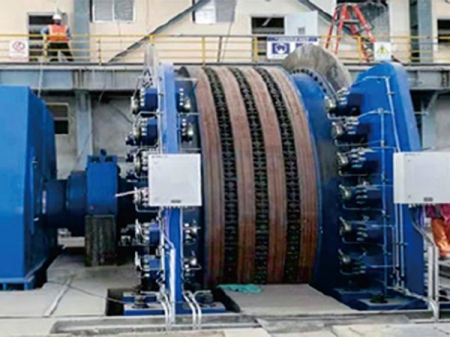
Mine Hoists


As a global reliable manufacturer and supplier of mineral processing equipment, CITIC Heavy Industries (CITIC HIC) has accumulated more than 60 years of experience in engineering and manufacturing of mine hoisting equipment. Over 7,000 sets of mine hoist system we have produced means we understand the system structure and have the ability to provide customer worldwide with safe, reliable, energy-saving and high-efficiency mine hoist solutions.
Key Features of CITIC HIC's Complete Mine Hoist System
- CITIC HIC is a leading company specialized in the design and manufacture of complete mine hoisting systems and mechanical, hydraulic and electrical systems in the domastic market
- Full-process automatic control technology
- High-power single-drive / dual-drive transmission system can solve the needs of large mining sites
- Constant torque control and multi-channel hydraulic braking systems ensure the safe operation of hoisting equipment
- Independently developed core technologies of mechanical, hydraulic and electrical systems provide high reliability at all events
- Remote monitoring and intelligent fault diagnosis technology helps maximize working efficiency
- One-stop service for quick response to users' needs regarding mechanical, hydraulic and electrical systems
Structural Advantages of Mine Hoist
CITIC HIC's mine hoists are provided with diameter range of Ø1.3-Ø6.5m
Various options of mine hoist transmission system
Manufacturing Capacity of Large-scale Mine Hoist
From 2000 to date, CITIC HIC has manufactured more than 200 mine hoists of over Ø4.5m in diameter, and more than 16 mine hoists of over 1000m in hoisting depth among which the Ø6.5m multi-rope friction mine hoist is the largest mine hoist in the domastic market.
| Model | Friction wheel diameter | Friction coefficient | Steel wire rope | Max. lifting speed | Head sheave diameter | Reducer model | Rotating part | Displacement weight of head sheave | Dimensions | ||||
| Max. static tension differential | Max. static tension | Max. diameter | Spacing | with reducer | without reducer | Displacement weight (excluding motor and guide wheel) | |||||||
| m | kN | kN | mm | mm | m/s | m/s | m | t | t | m | |||
JKMD-1.6×4 Ⅰ | 1.60 | 0.25 | 30 | 105 | 16 | 250 | 8.0 | - | 1.60 | ZZDP560 | 2.8 | 2×1.56 | 5.2×3.3×2.2 |
JKMD-1.85×4 Ⅰ | 1.85 | 45 | 155 | 20 | 10.0 | 16.0 | 1.85 | ZZDP710 | 6.2 | 2×2.1 | 6.2×3.8×2.5 | ||
JKMD-2×4 Ⅰ | 2.00 | 55 | 180 | 22 | 2.00 | 6.3 | 2×2.5 | 6.6×3.9×2.7 | |||||
JKMD-2.25×2 Ⅰ | 2.25 | 40 | 115 | 24 | 300 | 2.25 | ZZDP630 | 5.6 | 2×1.9 | 5.5×4.2×2.8 | |||
JKMD-2.25×4 Ⅰ | 65 | 215 | ZZDP800 | 6.3 | 2×2.6 | 6.8×4.2×2.8 | |||||||
JKMD-2.8×4 Ⅰ | 2.80 | 100 | 335 | 30 | 15.0 | 2.80 | ZZDP1000 | 10.8 | 2×3.4 | 7.5×4.8×2.65 | |||
JKMD-2.8×4 Ⅲ | - | 8.5 | 4.7×4.8×2.65 | ||||||||||
JKMD-3×4 Ⅰ | 3.00 | 140 | 450 | 32 | 3.00 | ZZDP1120 | 15.5 | 2×3.7 | 8.6×4.95×3.7 | ||||
JKMD-3×4 Ⅲ | - | 8.8 | 4.7×4.95×3.7 | ||||||||||
JKMD-3.25×4 Ⅰ | 3.25 | 160 | 520 | 36 | 3.25 | ZZDP1250 | 14.8 | 2×4.0 | 8.5×5.0×3.8 | ||||
JKMD-3.25×4 Ⅲ | - | 12.0 | 5.5×5.4×3.9 | ||||||||||
JKMD-3.5×4 Ⅰ | 3.50 | 180 | 570 | 38 | 3.50 | ZZDP1250 | 15.5 | 2×6.0 | 8.2×5.4×4.2 | ||||
JKMD-3.5×4 Ⅲ | - | 14.0 | 5.6×5.6×4.2 | ||||||||||
JKMD-4×4 Ⅰ | 4.00 | 270 | 770 | 44 | 350 | 4.00 | 23.6 | 2×8.9 | 10.5×6×4.7 | ||||
JKMD-4×4 Ⅲ | 20.5 | 6.0×4.7×4.7 | |||||||||||
JKMD-4.5×4 Ⅲ | 4.50 | 340 | 980 | 50 | 4.50 | 28.0 | 2×10.6 | 6.2×5.3×5.3 | |||||
JKMD-5×4 Ⅲ | 5.00 | 400 | 1250 | 54 | 5.00 | 30.0 | 2×14.0 | 6.3×5.7×5.7 | |||||
JKMD-5.5×4 Ⅲ | 5.50 | 450 | 1450 | 60 | 5.50 | 36.7 | 2×16.4 | 6.5×6.1×6.1 | |||||
JKMD-5.5×4 Ⅳ | 2×17.0 | 8.5×6.1×6.1 | |||||||||||
JKMD-5.7×4 Ⅳ | 5.70 | 470 | 1550 | 62 | 5.70 | 55.0 | 2×22.5 | 8.5×6.3×6.3 | |||||
JKMD-6×4 Ⅲ | 6.00 | 500 | 1650 | 64 | 6.00 | 42.5 | 2×23.0 | 6.5×6.6×6.6 | |||||
JKMD-6×4 Ⅳ | 60.0 | 9.0×6.6×6.6 | |||||||||||
JKMD-6.2×4 Ⅲ | 6.20 | 1700 | 66 | 6.20 | 45.5 | 2×23.5 | 6.5×6.8×6.8 | ||||||
Shaft Tower Type Multi-rope Friction Hoist
| Model | Friction wheel diameter m | Friction coefficient | Steel wire rope | Max. lifting speed | Guide wheel diameter | Reducer model | Displacement weight of rotating part (excluding motor and guide wheel) | Displacement weight of guide wheel | Dimensions | |||||
| Max. static tension differential | Max. static tension | Max. diameter | Spacing | |||||||||||
| With guide wheel | Without guide wheel | with reducer | without reducer | |||||||||||
| kN | kN | mm | mm | m/s | m | t | t | m | ||||||
JKM-1.3×4 I | 1.3 | 0.25 | 30 | — | 105 | 16 | 200 | 5 | 16 | — | ZZDP560 | 2.86 | — | 5×3.2×1.83 |
JKM-1.6×4 I | 1.6 | 40 | — | 150 | 20 | 8 | 4 | 6.4×3.6×2.1 | ||||||
JKM-1.85×4 I | 1.85 | 45/50 | 150 | 165 | 22 | 10 | 1.85 | ZZDP710 | 5.8 | 1.4 | 6.7×3.7×2.5 | |||
JKM-2×4 I | 2 | 55 | 180 | 2 | 6.1 | 1.45 | 6×3.8×2.64 | |||||||
JKM-2×5 I | 55 | 230 | 24 | 2 | 6.5 | 2.2 | 6.2×3.8×2.64 | |||||||
JKM-2.25×2 I | 2.25 | 30 | 105 | 300 | 2.25 | ZZDP 560 | 4.5 | 1.35 | 4.08×4.1×2.8 | |||||
JKM-2.25×4 I | 65 | 215 | 200 | ZZDP 800 | 6.2 | 1.5 | 6.3×4.2×2.8 | |||||||
JKM-2.8×4 I | 2.8 | 100 | 335 | 30 | 250 | 15 | 2.8 | ZZDP1000 | 9.5 | 2.65 | 7.5×4.8×3.6 | |||
JKM-2.8× 4Ⅲ | — | 9.7 | 2.8 | 5×4.9×3.6 | ||||||||||
JKM-2.8×6Ⅰ | 160 | 520 | ZZDP1120 | 11.6 | 3.7 | 8.5×4.9×3.4 | ||||||||
JKM-2.8× 6Ⅲ | — | 12 | 6×4.9×3.4 | |||||||||||
JKM-3×4Ⅰ | 3 | 140 | 450 | 32 | 300 | 3 | ZZDP1120 | 15.5 | 4.5 | 8.6×4.95×3.7 | ||||
JKM-3×4Ⅰ | — | 12.5 | 4.8 | 5×5.1×3.7 | ||||||||||
JKM-3.25×4Ⅰ | 3.25 | 160 | 520 | 36 | 3.25 | ZZDP1250 | 13.8 | 5 | 8.5×5.2×4.1 | |||||
JKM-3.25×4Ⅲ | — | 12.5 | 5.3×5.2×4.1 | |||||||||||
JKM-3.5×4Ⅰ | 3.5 | 180 | 570 | 38 | 3.5 | ZZDP1250 | 15.2 | 5.2 | 8.5×5.4×4.2 | |||||
JKM-3.5× 4Ⅲ | — | 14.2 | 5.5×5.4×4.2 | |||||||||||
JKM-3.5× 6Ⅲ | 270 | 860 | — | 21.1 | 6.5 | 7×5.4×4.2 | ||||||||
JKM-4×4Ⅰ | 4 | 770 | 44 | 4 | 23.5 | 5.6 | 10.5×4.7×4.7 | |||||||
JKM-4× 4Ⅲ | 20.2 | 5.8×4.7×4.7 | ||||||||||||
JKM-4× 6Ⅲ | 340 | 1200 | 27.5 | 7.5 | 6.5×4.7×4.7 | |||||||||
JKM-4.5× 4Ⅲ | 4.5 | 980 | 50 | 4.5 | 28.1 | 7.7 | 6.1×5.3×5.3 | |||||||
JKM-4.5×6Ⅲ | 440 | 1450 | 33.3 | 11.9 | 6.5×5.3×5.3 | |||||||||
JKM-4.5×6Ⅳ | 34.1 | 8.6×5.3×5.3 | ||||||||||||
JKM-4.6× 6Ⅲ | 4.6 | 1500 | 52 | 4.6 | 35.2 | 13 | 6.5×5.4×5.4 | |||||||
JKM-4.6×6Ⅳ | 36 | 8.6×5.4×5.4 | ||||||||||||
JKM-5× 4Ⅲ | 5 | 400 | 1500 | 54 | 5 | 30.5 | 14.1 | 6.1×5.8×5.8 | ||||||
JKM-5× 6Ⅲ | 500 | 1650 | 38.1 | 16.2 | 6.5×5.8×5.8 | |||||||||
JKM-5×6Ⅳ | 40.1 | 8.6×5.8×5.8 | ||||||||||||
JKM-5.5× 4Ⅲ | 5.5 | 1500 | 60 | 350 | 5.5 | 40 | 15.2 | 7.2×6.3×6.3 | ||||||
JKM-5.5×4Ⅳ | 42.5 | 9.4×6.3×6.3 | ||||||||||||
JKM-5.5× 6Ⅲ | 600 | 2000 | 50.5 | 18.6 | 8.2×6.3×6.3 | |||||||||
JKM-5.5×6Ⅳ | 54 | 10.5×6.3×6.3 | ||||||||||||
Notes
1. The parameters in the above table are for reference only for model selection.
2. Nominal gear ratio of reducer should be preferred in 7.35, 10.5 and 11.5.
| Model | Drum | Steel wire rope | Max. lifting height or inclined length | Max. lifting speed | Reducer | Motor speed (less than) | Displacement weight of rotating part (excluding motor and head sheave) | Dimensions | ||||||
| Quantity | Diameter | Width | Max. static tension | Max. diameter | Single-layer winding | Two-layer winding | Three-layer winding | Model | Preferred reducer gear ratio | |||||
| m | kN | mm | m | m/s | r/min | kg | m | |||||||
JK-2×1.5 | 1 | 2 | 1.5 | 60 | 25 | 295 | 586 | 914 | 5.2 | ZZL710 | 20 | 1000 | 6600 | Ø2.6×7.2 |
JK-2×1.8 | 1.8 | 366 | 730 | 1132 | 31.5 | 7200 | Ø2.6×8 | |||||||
JK-2.5×2 | 2.5 | 2 | 90 | 31 | 403 | 802 | 1245 | 4.9 | XL-30 | 20 | 750 | 14900 | Ø3.1×8.3 | |
| 31.5 | ||||||||||||||
JK-2.5×2.3 | 2.3 | 473 | 944 | 1460 | 20 | 14500 | Ø3.1×8.6 | |||||||
| 31.5 | ||||||||||||||
JK-3×2.2 | 3 | 2.2 | 130 | 37 | 447 | 887 | 1378 | 5.9 | ZZL1000 | 20 | 19000 | Ø3.6×9.6 | ||
| 31.5 | ||||||||||||||
JK-3×2.5 | 2.5 | 518 | 1030 | 1595 | 20 | 19600 | Ø3.6×10.2 | |||||||
| 31.5 | ||||||||||||||
JK-3.5×2.5 | 3.5 | 2.5 | 170 | 43 | 513 | 1017 | — | 6.9 | ZZL1250 | 20 | 30000 | Ø4.15×10.2 | ||
| 31.5 | ||||||||||||||
JK-3.5×2.8 | 2.8 | 584 | 1161 | 20 | 31000 | Ø4.15×11 | ||||||||
| 31.5 | ||||||||||||||
JK-4×2.7 | 4 | 2.7 | 245 | 48 | 568 | 1124 | 6.3 | ZZ L 1400 | 20 | 600 | 35000 | Ø4.6×12 | ||
| 31.5 | ||||||||||||||
JK-4.5×3 | 4.5 | 3 | 280 | 56 | 610 | 1207 | 7 | ZZ L 1600 | 20 | 38000 | Ø4.9x15.5 | |||
| 31.5 | ||||||||||||||
| 20 | ||||||||||||||
| 31.5 | ||||||||||||||
Notes
1. The max. lifting height or inclined length is a reference value calculated according to the max. diameter of steel wire rope.
2. The max. lifting speed is obtained by calculating single-layer winding speed.
| Model | Drum | Steel wire rope | Max. lifting height or inclined length | Max. lifting speed | Reducer | Motor speed (less than) | Displacement weight of rotating part (excluding motor and head sheave) | Dimensions | ||||||||
| Quantity | Diameter | Width | Distance between two drums | Max. static tension | Max. static tension differential | Max. diameter | Single-layer winding | Two-layer winding | Three-layer winding | Model | Preferred reducer gear ratio | |||||
| m | mm | kN | mm | m | m/s | r/min | kg | m | ||||||||
2JK-2×1 | 2 | 2 | 1 | 1090 | 60 | 40 | 25 | 177 | 346 | 550 | 7 | ZZDP630B,ZZL630 | 11.2,20/31.5 | 750 | 9740 | Ø2.6×8.2 |
2JK-2×1.25 | 1.3 | 1340 | 236 | 467 | 733 | 10000 | Ø2.6×8.5 | |||||||||
2JK-2.5×1.2 | 2.5 | 1.2 | 1290 | 90 | 55 | 31 | 215 | 422 | 670 | 8.8 | ZZDP710,ZZL710 | 11.2,20/31.5 | 14000 | Ø3.1×9.2 | ||
2JK-2.5×1.5 | 1.5 | 1590 | 286 | 564 | 885 | 14700 | Ø3.1×9.5 | |||||||||
2JK-3×1.5 | 3 | 130 | 80 | 37 | 282 | 553 | 873 | 10.5 | ZZDP900A,XL-30 | 11.2,20/31.5 | 23000 | Ø3.6×9.5 | ||||
2JK-3×1.8 | 1.8 | 1890 | 353 | 697 | 1090 | 23500, 23800 | Ø3.6×10.5, Ø3.6×10 | |||||||||
2JK-3.5×1.7 | 3.5 | 1.7 | 1790 | 170 | 115 | 43 | 324 | 635 | - | 12.6 | ZZDP1000A,ZZL1000 | 11.2,20 | 27000 | Ø4.1×12 | ||
2JK-3.5×2.1 | 2.1 | 2190 | 419 | 823 | 28000 | Ø4.1×13.5 | ||||||||||
2JK-4×2.1 | 4 | 245 | 165 | 50 | 423 | 831 | 11.2 | ZZDP1250,ZZL1250 | 11.2,20 | 600 | 41000 | Ø4.5×13 | ||||
2JK-5×2.3 | 5 | 2.3 | 2390 | 350 | 230 | 62 | 458 | 895 | 14 | ZZDP1600,ZZL1600 | 65000 | Ø5.6×20.5 | ||||
2JK-6×2.5 | 6 | 2.5 | 2590 | 500 | 320 | 75 | 472 | 920 | ZZDP1800,ZZL1800 | 11.2,20 | 500 | 95000 | Ø6.8×20.5 | |||
Notes
1. The max. lifting height or inclined length is a reference value calculated according to the max. diameter of steel wire rope.
2. The max. lifting speed is obtained by calculating single-layer winding speed.
| Model | Drum | Steel wire rope | Max. lifting height or inclined length | Max. lifting speed | Reducer gear ratio | Motor speed | ||||||
| Quantity | Diameter | Width | Max. static tension differential | Max. static tension differential | Max. diameter | Single-layer winding | Two-layer winding | Three-layer winding | ||||
| m | kN | kN | mm | m | m/s | r/min | ||||||
JK Z-2.8×2.2 | 1 | 2.8 | 2.2 | 185 | 185 | 40 | 380 | 795 | 1250 | 5.68 | 15.5 | 600 |
JK Z-3.2× 3 | 3.2 | 3 | 200 | 200 | 42 | 590 | 1230 | 1920 | 6.48 | |||
JK Z-3.6× 3 | 3.6 | 220 | 220 | 44 | 640 | 1320 | 2060 | 7.29 | ||||
JK Z-4× 3 | 4 | 270 | 270 | 48 | 650 | 1340 | 2100 | 7.39 | 17 | |||
JK Z-4× 3.5 | 3.5 | 290 | 290 | 50 | 740 | 1530 | 2380 | 7.85 | 16 | |||
JK Z-4.5×3.7 | 4.5 | 3.7 | 360 | 360 | 56 | 790 | 1630 | 2530 | 7.94 | 17.8 | ||
JK Z-5× 4 | 5 | 4 | 410 | 410 | 62 | 860 | 1770 | 2760 | 7.85 | 20 | ||
JK Z-5.5× 5 | 5.5 | 5 | 500 | 500 | 68 | 1100 | 2200 | 3500 | 8.64 | |||
2JKZ-3×1.8 | 2 | 3 | 1.8 | 185 | 155 | 40 | 330 | 670 | 1070 | 6.08 | 15.5 | |
2JKZ-3.6×1.85 | 3.6 | 1.85 | 200 | 180 | 42 | 380 | 800 | 1270 | 7.29 | |||
2JKZ-4×2.65 | 4 | 2.65 | 290 | 255 | 50 | 540 | 1100 | 1760 | 8.1 | |||
2JKZ-5× 3 | 5 | 3 | 410 | 290 | 62 | 620 | 1290 | 2020 | 7.85 | 20 | ||
2JKZ-5.5× 4 | 5.5 | 4 | 500 | 410 | 68 | 860 | 1780 | 2770 | 8.64 | |||
| Model | Drum | Steel wire rope | Max. lifting height or inclined length | Max. lifting speed | Reducer | Motor speed (less than) | Displacement weight of rotating part (excluding motor and head sheave) | Dimensions | |||||||
| Quantity | Diameter | Width | Max. static tension | Max. static tension differential | Max. diameter | Single-layer winding | Two-layer winding | Three-layer winding | Model | Preferred reducer gear ratio | |||||
| m | kN | kN | mm | m | m | m/s | r/mⅠn | kg | m | ||||||
JTPB-1.6×1.2P | 1 | 1.6 | 1.2 | 45 | 45 | 26 | 162 | 378 | 600 | 4 | ZZL560 | 20 | 1000 | 4500 | Ø2×4.3 |
| 31.5 | |||||||||||||||
JTPB-1.6×1.5P | 1.5 | 216 | 487 | 766 | 20 | Ø2×5.3 | |||||||||
| 31.5 | |||||||||||||||
2JTPB-1.6×0.9P | 2 | 0.9 | 30 | 108 | 169 | 434 | 20 | 3900 | Ø2×6.3 | ||||||
| 31.5 | |||||||||||||||
2JTPB-1.6×1.2P | 1.2 | 162 | 378 | 600 | 20 | Ø2×7.3 | |||||||||
| 31.5 | |||||||||||||||
JKB-2×1.5P | 1 | 2 | 1.5 | 62 | 62 | 32 | 493 | 5.2 | ZZL710 | 20 | 6600 | Ø2.6×7.2 | |||
| 244 | 774 | 31.5 | |||||||||||||
JKB-2×1.8P | 1.8 | 299 | 604 | 942 | 20 | 7200 | P2.6×8 | ||||||||
| 31.5 | |||||||||||||||
JKB-2.5×2P | 2.5 | 2 | 83 | 83 | 40 | 329 | 665 | 1041 | 5 | ×L-30 | 20 | 750 | 14000 | Ø2.9×8.3 | |
| 31.5 | |||||||||||||||
JKB-2.5×2.3P | 2.3 | 366 | 776 | 1210 | 20 | 14500 | Ø2.9×9 | ||||||||
| 31.5 | |||||||||||||||
JKB-3×2.2P | 3 | 2.2 | 135 | 135 | 50 | 348 | 703 | 1106 | 6 | ZZL1000 | 20 | 19000 | Ø3.4×9.6 | ||
| ZZL1000A | 31.5 | ||||||||||||||
JKB-3× 2.5P | 2.5 | 396 | 810 | 1250 | ZZL1000 | 20 | 19600 | Ø3.4×10.2 | |||||||
| ZZL1000A | 31.5 | ||||||||||||||
2JKB-2×1P | 2 | 2 | 1 | 62 | 40 | 32 | 153 | 308 | 494 | 7 | ZZDP630B | 11.2 | 9740 | Ø2.6×8.2 | |
| ZZL630 | 20 | ||||||||||||||
| 31.5 | |||||||||||||||
2JKB-21.25P | 1.25 | 199 | 401 | 634 | ZZDP630B | 11.2 | 10000 | Ø2.6×8.5 | |||||||
| ZZL630 | 20 | ||||||||||||||
| 31.5 | |||||||||||||||
2JKB-2.51.2P | 2.5 | 1.2 | 83 | 65 | 40 | 183 | 369 | 591 | 8.8 | ZZDP710 | 11.2 | 14000 | Ø3×9.2 | ||
| ZZL710 | 20 | ||||||||||||||
| 31.5 | |||||||||||||||
2JKB-2.5*1.5P | 1.5 | 238 | 480 | 760 | ZZDP710 | 20 | |||||||||
| ZZL710 | 31.5 | 14700 | Ø3×9.5 | ||||||||||||
2JKB-3×1.5P | 3 | 135 | 90 | 50 | 224 | 450 | 722 | 10.5 | ZZDP900A | 11.2 | 23000 | Ø3.6×9.5 | |||
| ×L-30 | 20 | ||||||||||||||
| 31.5 | |||||||||||||||
2JKB-3× 1.8P | 1.8 | 277 | 558 | 886 | ZZDP900A | 11.2 | 23500 | Ø3.6×10.5 | |||||||
| 20 | |||||||||||||||
| ×L-30 | 31.5 | ||||||||||||||
2JKB-3.5× 1.7P | 3.5 | 1.7 | 170 | 115 | 303 | 608 | 966 | 12.3 | ZZL1000 | 11.2 | 27000 | Ø4.1×12 | |||
| ZZL1000A | 20 | ||||||||||||||
2JKB-3.5× 2.1P | 2.1 | 386 | 776 | 1221 | ZZL1000 | 11.2 | 27800 | Ø4.1×13.5 | |||||||
| ZZL1000A | 20 | ||||||||||||||
Notes
1. The max. lifting height or inclined length is a reference value calculated according to the max. diameter of steel wire rope.
2. The max. lifting speed is obtained by calculating single-layer winding speed.
| Model | Drum | Max. lifting height (when wire rope with max. diameter) | Steel wire rope | Max. lifting speed | Main motor power | Max. pressure of hydraulic system | ||||||||
| Quantity | Diameter | Width | Single-layer winding | Two-layer winding | Three-layer winding | Max. static tension | Max. static tension differential | Max. diameter | Min. breaking strength | |||||
| People load | Item load | |||||||||||||
| pc | mm | m | kN | kN | mm | kN | kN | m/s | kw | MPa | ||||
JKYB-4×3J | 1 | 4000 | 3000 | 653 | 1344 | 2101 | 180 | 180 | 48 | 1620 | 1170 | ≤5 | ≤1200 | 32 |
JKYB-4× 3.5J | 3500 | 776 | 1593 | 2478 | ||||||||||
2JKYB-4× 2.1J | 2 | 2100 | 431 | 896 | 1422 | 120 | ||||||||
2JKYB-4×2.5J | 2500 | 529 | 1095 | 1724 | ||||||||||
JKYB-3.5× 2.5J | 1 | 3500 | 2500 | 505 | 1048 | 1647 | 150 | 150 | 44 | 1350 | 975 | ≤5 | ≤1000 | |
JKYB-3.5×2.8J | 2800 | 575 | 1190 | 1862 | ||||||||||
JKYB-3.5×3J | 3000 | 622 | 1284 | 2005 | ||||||||||
2JKYB-3.5×1.7J | 2 | 1700 | 318 | 670 | 1074 | 100 | ||||||||
2JKYB-3.5×2.1J | 2100 | 412 | 859 | 1360 | ||||||||||
2JKYB-3.5×2.5J | 2500 | 505 | 1048 | 1647 | ||||||||||
JKYB-3×2.2J | 1 | 3000 | 2200 | 445 | 928 | 1459 | 120 | 120 | 38 | 1080 | 780 | ≤4.5 | ≤800 | |
JKYB-3×2.5J | 2500 | 516 | 1071 | 1676 | ||||||||||
JKYB-3× 2.8J | 2800 | 587 | 1214 | 1893 | ||||||||||
2JKYB-3× 1.5J | 2 | 1500 | 281 | 595 | 954 | 80-120 | ||||||||
2JKYB-3× 1.8J | 1800 | 351 | 738 | 1171 | ||||||||||
2JKYB-3×2J | 2000 | 398 | 833 | 1315 | ||||||||||
JKYB-2.8×2J | 1 | 2800 | 2000 | 339 | 715 | 1135 | 130 | 130 | 40 | 1170 | 845 | ≤4 | ≤800 | |
JKYB-2.8×2.3J | 2300 | 401 | 839 | 1324 | ||||||||||
JKYB-2.8×2.5J | 2500 | 442 | 922 | 1449 | ||||||||||
2JKYB-2.8×1.2J | 2 | 1200 | 176 | 384 | 632 | 85-130 | ≤600 | |||||||
2JKYB-2.8×1.5J | 1500 | 237 | 508 | 821 | ||||||||||
JKYB-2.52J | 1 | 2500 | 2000 | 359 | 754 | 1191 | 90 | 90 | 34 | 810 | 585 | ≤400 | ||
JKYB-2.5×2.3J | 2300 | 423 | 883 | 1386 | ||||||||||
JKYB-2.5× 2.5J | 2500 | 465 | 969 | 1516 | ||||||||||
2JKYB-2.5×1.2J | 2 | 1200 | 189 | 411 | 670 | 55-90 | ≤280 | |||||||
2JKYB-2.5× 1.5J | 1500 | 253 | 540 | 865 | ||||||||||
2JKYB-2.5×2J | 2000 | 359 | 754 | 1191 | ||||||||||
JKYB-2× 1.5J | 1 | 2000 | 1500 | 255 | 546 | 869 | 60 | 28 | 540 | 390 | ≤3.5 | ≤280 | ||
JKYB-2×1.8J | 1800 | 318 | 672 | 1062 | 60 | |||||||||
2JKYB-2×1J | 2 | 1000 | 151 | 334 | 547 | 40-60 | ≤200 | |||||||
2JKYB-2× 1.25J | 1250 | |||||||||||||
| 203 | 440 | 708 | ||||||||||||
JT YB-1.6× 1.2J | 1 | 1600 | 1200 | 179 | 392 | 631 | 45 | 45 | 24 | 405 | 292.5 | ≤3 | ≤200 | |
JT YB-1.6× 1.5J | 1500 | 237 | 509 | 809 | ||||||||||
2JTYB-1.6× 0.9J | 2 | 900 | 121 | 274 | 452 | 30-45 | ≤160 | |||||||
352JTYB-1.6× 1.2J | 1200 | 179 | 392 | 631 | ||||||||||
| Model | Drum | Max. static tension of wire rope kN | Max. static tension differential of wire rope kN | Max. Diameter of wire rope mm | Max. lifting height or inclined length M | |
| Diameter m | Width m | |||||
JKD-4×1.9 | 4 | 1.9 | 690 | 690 | 50 | 1200 |
JKD-4.5×2.2 | 4.5 | 2.2 | 870 | 870 | 56 | 1400 |
JKD-5×2.5 | 5 | 2.5 | 1070 | 1070 | 62 | 1600 |
JKD-5.5×2.8 | 5.5 | 2.8 | 1290 | 1290 | 68 | 1800 |
JKD-6×3.1 | 6 | 3.1 | 1570 | 1570 | 75 | 2000 |
JKD-6.5×3.4 | 6.5 | 3.4 | 1830 | 1830 | 81 | 2200 |
2JKD-4×1.9 | 4 | 1.9 | 690 | 480 | 50 | 1200 |
2JKD-4.5×2.2 | 4.5 | 2.2 | 870 | 680 | 56 | 1400 |
2JKD-5×2.5 | 5 | 2.5 | 1070 | 810 | 62 | 1600 |
JKD-5.5×2.8 | 5.5 | 2.8 | 1290 | 1020 | 68 | 1800 |
2JKD-6×3.1 | 6 | 3.1 | 1570 | 1290 | 75 | 2000 |
2JKD-6.5×3.4 | 6.5 | 3.4 | 1830 | 1560 | 81 | 2200 |
Chahasu Coal Mine in Inner Mongolia, Auxiliary Shaft (JKM-5×6PⅢ)
Max. static tension: 1700kN
Max. static tension differential: 340kN
Max. lifting speed: 9.42m/s
Motor power: 3000kW
Huaneng Group's Hetaoyu Mine in Gansu, Auxiliary Shaft (JKMD-6.2×4PⅢ)
Max. static tension: 1700kN
Max. static tension differential: 340kN
Max. lifting speed: 11.3m/s
Motor power: 3000kW
Huainan Mining Group's Zhangji Coal Mine, Main Shaft (JKMD-5.7×4PⅣ)
Max. static tension: 1500kN
Max. static tension differential: 440kN
Max. lifting speed: 14m/s
Motor power: 2×3000kW
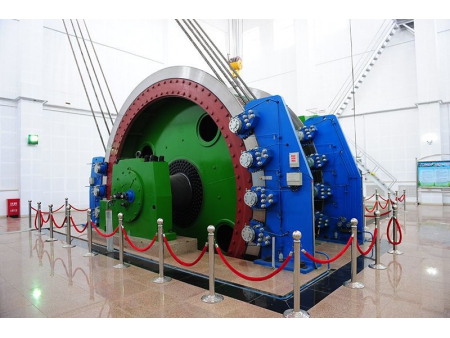
State Administration of Work Safety's Security Access Test Bench (JKMD-6.5×6PⅣ)
Max. static tension: 2000kN
Max. static tension differential: 600kN
Max. lifting speed: 20m/s
Motor power: 10000kW
SK Mine Vertical Shaft Project in India (JKMD-5.5x4PⅢ)
Max. static tension differential: 350kN
Max. lifting speed: 11.8m/s
Max. lifting height: 1041.36m
Motor power: 4400kW
Chambishi Copper Mine in Zambia (JKMD-5.7x4PⅢ)
Max. static tension differential: 185kN
Max. lifting speed: 9.6m/s
Max. lifting height: 675m
Motor power: 6300kW
- Manufacturing
Casting and Forging Capacity
We have four production lines that have the capacity to produce large steel castings, large high-value forgings, large annular parts and large non-ferrous metal parts respectively. - Service
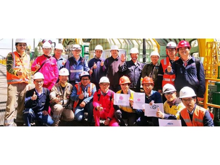
Lifetime service
With state-of-the-art technology and rich experience, CITIC HIC works through each critical step to individualize the optimal process and performance as per customer needs. Our lifetime service covers equipment installation, testing, maintenance, refurbishing, remote monitoring & diagnosis, upgrading & retrofitting, and performance guarantee.


