Crossflow Cooling Tower (Closed Circuit Steel Cooling Tower)

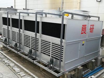
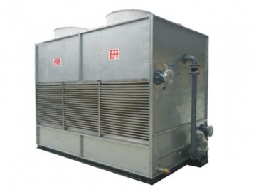

The heat exchanging process in the crossflow cooling tower is completed in a clean closed circuit. Multiple material selections and configurations of the heat exchanger coil ensure the closed circuit heat rejection equipment is suitable for applications in industrial and heating ventilation air conditioning (HVAC) fields. This cooling tower system reduces scaling that occurs during technical processes, thus ensuring a constant process performance under long term operations, and ensures a long service life.
Working fluid (water, oil or other liquids) flows in the curved coil pipe, while the spray water is transferred from the bottom basin to the PVC distribution pipe via the water pump, then sprayed through the nozzle to the coil pipe. Throughout this, the air comes into full contact with the coil surface. Through an evaporation heat exchange, the coil pipe heat is reduced, which reduces the overall temperature.
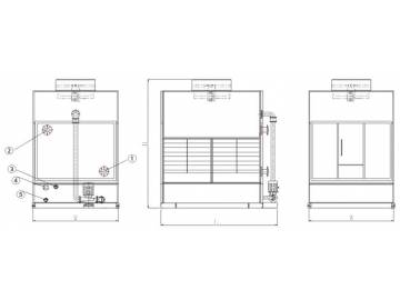
All the following dimensions are referenced in relation to standard evaporative cooling products. In addition, we can also perform non-standard design depending on specific customer requirements.
1. Water inlet
2. Water outlet
3. Water filler pipe
4. Overflow pipe
5. Drain pipe
- Inlet water temperature: T1=37℃
- Outlet water temperature: T2=32℃
- Wet bulb temperature: TWB=28℃
- Dry bulb temperature: T=31.5℃
- Atmospheric pressure: P=99.4KPa
| Model | Overall dimension (mm) | Fan power | Pump power | Water inlet/outlet pipe diameter | Water filler pipe diameter | Drain pipe diameter | Transport weight | ||
| L | W | H | (KW) | (KW) | (mm) | (mm) | (mm) | (Kg) | |
| LYH-6 | 1360 | 1030 | 1850 | 1.1 | 0.2 | 32 | 25 | 32 | 290 |
| LYH-8 | 1360 | 1030 | 1850 | 1.1 | 0.2 | 32 | 25 | 32 | 310 |
| LYH-10 | 1360 | 1030 | 1850 | 1.1 | 0.55 | 32 | 25 | 32 | 335 |
| LYH-15 | 2350 | 1280 | 2350 | 1.1 | 0.55 | 50 | 25 | 32 | 600 |
| LYH-20 | 2350 | 1280 | 2450 | 1.5 | 0.55 | 50 | 25 | 32 | 725 |
| LYH-25 | 2350 | 1280 | 2500 | 1.5 | 0.55 | 50 | 25 | 32 | 815 |
| LYH-30 | 2660 | 1400 | 2500 | 2.2 | 0.75 | 65 | 25 | 32 | 925 |
| LYH-35 | 2660 | 1400 | 2600 | 2.2 | 0.75 | 65 | 25 | 32 | 1010 |
| LYH-40 | 2660 | 1400 | 2600 | 3 | 0.75 | 80 | 25 | 50 | 1100 |
| LYH-50 | 2800 | 1750 | 2650 | 3 | 0.75 | 80 | 25 | 50 | 1400 |
| LYH-60 | 2800 | 1750 | 2700 | 4.4 | 0.75 | 100 | 32 | 50 | 1510 |
| LYH-70 | 2900 | 2060 | 2800 | 4.4 | 1.5 | 100 | 32 | 50 | 1900 |
Note: the above data applies to copper coils. Specific materials should be chosen based on fluid characteristics.
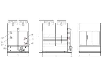
1. Water inlet
2. Water outlet
3. Water filler pipe
4. Overflow pipe
5. Drain pipe
- Inlet water temperature: T1=37℃
- Outlet water temperature: T2=32℃
- Wet bulb temperature: TWB=28℃
- Dry bulb temperature: T=31.5℃
- Atmospheric pressure: P=99.4KPa
| Model | Overall dimension (mm) | Fan power | Pump power | Water inlet/outlet pipe diameter | Water filler pipe diameter | Drain pip e diameter | Transport weight | ||
| L | W | H | (KW) | (KW) | (mm) | (mm) | (mm) | (Kg) | |
| LYH-80 | 3200 | 2060 | 2800 | 6 | 1.5 | 100 | 32 | 50 | 1990 |
| LYH-90 | 3200 | 2260 | 2800 | 8.8 | 2.2 | 125 | 32 | 50 | 2160 |
| LYH-100 | 3800 | 2260 | 3000 | 8.8 | 2.2 | 125 | 32 | 50 | 2320 |
| LYH-125 | 3800 | 2260 | 3050 | 8.8 | 2.2 | 100*2 | 32 | 50 | 2780 |
| LYH-150 | 4800 | 2500 | 3100 | 13.2 | 2.2 | 100*2 | 32 | 50 | 3511 |
| LYH-175 | 4800 | 2700 | 3150 | 13.2 | 3 | 125*2 | 32 | 50 | 4232 |
| LYH-200 | 4800 | 2700 | 3150 | 17.6 | 4.4 | 125*2 | 32 | 65 | 4460 |
| LYH-225 | 5400 | 3000 | 3200 | 17.6 | 4.4 | 100M | 32 | 65 | 4900 |
| LYH-250 | 5400 | 3000 | 3650 | 17.6 | 4.4 | 100M | 32 | 65 | 5260 |
| LYH-275 | 6000 | 3200 | 6750 | 22 | 4.4 | 100*4 | 32 | 65 | 5718 |
| LYH-300 | 6000 | 3200 | 3950 | 22 | 4.4 | 100*4 | 32 | 65 | 5990 |
Note: the above data applies to copper coils. Specific materials should be chosen based on fluid characteristics.
")
")

")


