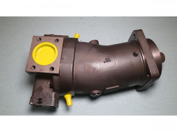
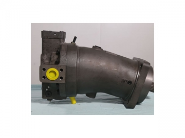
Bent Axis Piston Pump, A7V


Descriptions
1. OSA7V is a variable displacement pump with axial piston and bent axis design. The bent axis piston pump is used for hydrostatic transmissions in open circuit operation.
2. The flow is in proportion to the drive speed and the displacement and is steplessly variable at constant drive speed.
3. Thebent axis pump comes with a complete range of control devices for all kinds of control and adjustment.
4. It runs on mineral oil and fire resistant fluid.
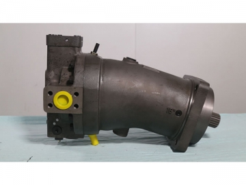
5. With large size and robust casing, the bent axis hydraulic pump can meet the working requirements in various extreme working conditions.
Applications
The OSA7V bent axis piston pump is mainly used in the hydraulic systems of metal forming machinery, natural gas refueling equipment, construction machinery (pile driver), etc.
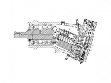
Structural Features
1. The axial piston pump is equipped with high performance rotating group and valve plate in spherical surface design, realizing automatic centering, low peripheral speed and high efficiency.
2. Drive shaft can bear radial load.
3. Long service life;
4. Low noise
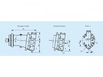
- Stroke limiter
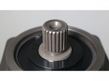
- Shaft end (Splined shaft)
Notes:
Casing drainage oil temperature is influenced by pressure and pump speed and is always higher than the circuit temperature. However, at no point in the circuit may the temperature exceed 90℃.
The minimum pressure at the suction port of the pump≥ 0.08MPa (Absolute pressure), and the drain pressure (Maximum allowable casing pressure) is 0.2MPa (absolute pressure). The pressure in the housing must be the same or greater than the external pressure to the shaft seal.
1. Inlet Operating Pressure Range (Absolute Pressure)
Minimum pressure: Ps min=0.08 bar
Maximum pressure: Ps max=0.2 bar
2. Outlet Operating Pressure Range
Nominal pressure: Pn=35 bar
Peak pressure: Pmax=40 bar
3. Technical Parameter List
(Nominal data, without considering mechanical efficiency and volumetric efficiency)
| Size | 20 | 28 | 40 | 55 | 58 | 80 | 78 | 107 | 117 | 160 | |||
| Displacement | Vgmax mL /r | 20.5 | 28.1 | 40.1 | 54.8 | 58.8 | 80 | 78 | 107 | 117 | 160 | ||
| Vgmin mL /r | 0 | 8.1 | 0 | 15.8 | 0 | 23.1 | 0 | 30.8 | 0 | 46.2 | |||
| Control devices ● = Available | LV | ● | ● | ● | ● | ● | ● | ● | ● | ● | ● | ||
| LVS | ● | ||||||||||||
| DR | ● | ● | ● | ● | ● | ||||||||
| DRS | ● | ||||||||||||
| MA | ● | ● | ● | ● | ● | ● | ● | ● | ● | ● | |||
| Max. Speed | 0.09MPa | nmax0.09 | r/min | 3800 | 2800 | 3200 | 2360 | 2850 | 2120 | 2540 | 1900 | 2240 | 1650 |
| 0.1 MPa | Nmax 0.1 | r/min | 4100 | 3000 | 3400 | 2500 | 3000 | 2240 | 2700 | 2000 | 2360 | 1750 | |
| 0.15MPa | Nmax 0.15 | r/min | 4750 | 3600 | 3750 | 3000 | 3350 | 2750 | 3000 | 2450 | 2650 | 2100 | |
| Max. Flow | Nmax0.09 | Qmax0.09 | L/min | 76 | 76 | 124 | 125 | 161 | 164 | 192 | 197 | 254 | 256 |
| Nmax0.1 | Qmax0.1 | L/min | 82 | 82 | 132 | 133 | 170 | 174 | 204 | 208 | 267 | 271 | |
| Nmax0.15 | Qmax0.15 | L/min | 94 | 98 | 146 | 160 | 190 | 213 | 227 | 254 | 300 | 326 | |
| Max. Power (△ p=35MPa) | Qmax0.09 | P max0.09 | KW | 45 | 46 | 75 | 75 | 97 | 99 | 116 | 119 | 153 | 154 |
| QmaxO.1 | P max0.1 | KW | 49 | 49 | 80 | 80 | 102 | 105 | 123 | 125 | 161 | 163 | |
| Qmax0.15 | Pmax0.15 | KW | 57 | 59 | 88 | 96 | 114 | 128 | 136 | 153 | 181 | 196 | |
| Flow | NE=1450r/min | Q | L/min | 28.8 | 39.5 | 56.4 | 77.1 | 82.3 | 112.5 | 109.7 | 150.5 | 164.6 | 225 |
| Power (△ p=35MPa) | NE=1450r/min | P | KW | 17 | 24 | 34 | 46 | 50 | 68 | 66 | 91 | 99 | 135 |
| Torque (△ p=10MPa) | Vgmax | M | Nm | 32.6 | 44.6 | 63.7 | 87 | 93.2 | 127.5 | 124 | 169.7 | 186 | 254 |
| Vgmin | M | Nm | - | 12.9 | - | 25.1 | - | 36.8 | - | 49 | - | 73.5 | |
| Torque (△ p=35MPa) | Vgmax | M | Nm | 114 | 156 | 223 | 305 | 326 | 446 | 431 | 594 | 651 | 889 |
| Vgmin | M | Nm | - | 45 | - | 88 | - | 129 | - | 171 | - | 257 | |
| Moment | J | kgm2 | 0.0017 | 0.0017 | 0.0052 | 0.0052 | 0.0109 | 0.0109 | 0.0167 | 0.0167 | 0.0322 | 0.0322 | |
| Weight | Kg | 19 | 19 | 28 | 28 | 44 | 44 | 53 | 53 | 76 | 76 | ||
| OS7V | 55 | LV | 1 | l L | Z | F | O | O |
| 1 | 2 | 3 | 4 | 5 | 6 | 7 | 8 | 9 |
| Axial piston, bent axis, variable | OS7V |
| Displacement mL /r | 20 | 28 | 40 | 55 | 58 | 80 | 78 | 107 | 117 | 160 |
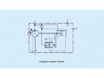
| Constant power control | LV |
| Constant power control with load sensing | LVS |
| Constant pressure control | DR |
| Constant pressure control with load sensing | DRS |
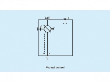
| Manual control | MA |
| --- | 1 |
| Clockwise | R |
| Counterclockwise | L |
| Splined shaft DIN 5480 | Z |
| Splined shaft GB 3478.1-83 | S |
| Keyed shaft GB1096-79 | P |
| Pressure port: SAE flange, on side Suction port: SAE flange, on side | F |
| Pressure port: threaded, on side Suction port: SAE flange, on side | G |
| 5SW none | O |
| Stroke limiter, mechanically adjustable (for LV and DR) | M |
| Stroke limiter, hydraulic (for LV) | H |
| None | O |
| With pressure cut-off | D |
Ordering Example: OS7V.55.LV.1 .L.Z.F.0.0
Axial piston variable displacement pump 0S7V, size 55. With constant power control, series 1.
Anti-clockwiserotation, splined shaft, SAE flange connections, without stroke limiter and auxiliary equipment.
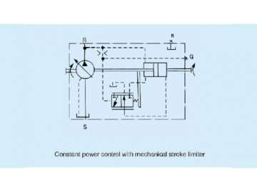
LV Constant power controlThe constant power control controls flow in relation to pressure, thereby maintaining hydraulic power constant. (Provided that the drive speed is constant)
P=p*Q/60= Constant
P~ power[KW]
p~ pressure[MPa]
Q~ flow[L/min]
Commencement of control: Min. 5MPa
Total power control can be realized by throttles via port G.
| No. | Model | Specifications |
| 1 | OS7V Bent Axis Pump | OS7V 40 LV(DR) 1R(L) P(Z;S)F(G)OO |
| 2 | OS7V 55 LV(DR) 1R(L) P(Z;S)F(G)OO | |
| 3 | OS7V 58 LV(DR) 1R(L) P(Z;S)F(G)OO | |
| 4 | OS7V 80 LV(DR) 1R(L) P(Z;S)F(G)OO | |
| 5 | OS7V 78 LV(DR) 1R(L) P(Z;S)F(G)OO | |
| 6 | OS7V 107 LV(DR) 1R(L) P(Z;S)F(G)OO | |
| 7 | OS7V 117 LV(DR) 1R(L) P(Z;S)F(G)OO | |
| 8 | OS7V 160 LV(DR) 1R(L) P(Z;S)F(G)OO |
Stroke Limiter
By means of a mechanical or hydraulic stroke limiter, the maximum displacement can be infinitely varied or limited. Adjustment range from Vgmax to Vgmin.
| Size | 20 | 40 | 58 | 78 | 117 |
| 28 | 55 | 80 | 107 | 160 | |
| Spindle Revolutions | 23 | 21 | 28 | 31 | 26 |
| Required Torque (approx. JNcm | 80 | 140 | 500 | 630 | - |
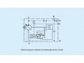
Constant power control with mechanical stroke limiterConstant power control with hydraulic stroke limiterHydraulic Stroke Limiter
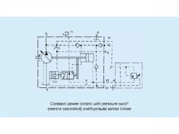
A pilot pressure (port X1) that is not less than 10% of the operating pressure is required for the hydraulic stroke limiter. Maximum allowable pressure at port X1 is 30MPa (for all sizes). If it is required to limit the flow at an operating pressure of less than 5MPa, an oil supply pressure that is not less than 5MPa must be applied at port X2 (pressure of port X1 is 10% pressure of port X2, namely 5MPa×10%=0.5MPa)
Auxiliary Equipment
Pressure cut-off
For all sizes with Vgmin=0
The pressure cut-off is a constant pressure control superposed on the constant power control and is carried out by means of a sequence valve. When the set maximum pressure is reached (adjustment range up to 315MPa), the valve opens and the flow is automatically reduced to zero. The sequence valve is mounted separately from the pump. It can be mounted on a subplate in any suitable location (remote control).
When using the constant power control with pressure cut-off unit, the pump control time will be approximately 3 times longer than that of constant pressure control pump.
Important: Port T from the sequence valve and port T1 from the pilot oil return line must be directly connected to the oil tank.
Ports
B Pressure port
S Suction port
G Port for summation power control line
X1 Pilot pressure port
X2 Remote control pressure port
A1,X3 Ports for remote control valve
T1 Pilot oil return port
R Airbleed port
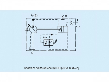
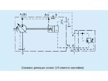
Constant power control with pressure cutoff (remote control) and hydraulic stroke limiterIn its control range, the constant pressure control device maintains the system pressure constant without impact by pump flow change. The variable displacement bent axis piston pump only supplies a necessary volume of fluid. If the operating pressure exceeds the preset valve, the pump is automatically swiveled back to a smaller angle.
The required pressure can be directly set on the pump (built in valve, standard) with 5-35MPa range. For remote control type, it can be set independently on the sequence valve with 5-31.5MPa range.
Constant pressure control DR (valve built-in)Constant pressure control DR (remote controlled)Note: Sequence valve and subplate should be ordered separately. The maximum single pipe length should not exceed 5m. Sequence valve Port T must be piped separately to tank. Pressure of the relief valve installed in the system for pressure protection must be 2MPa higher than the pressure of the constant pressure control.
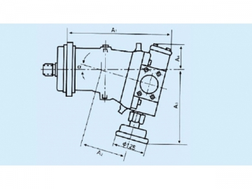
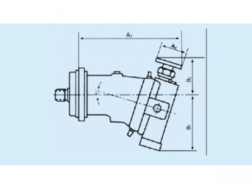
Constant Pressure Control DR Size (Standard, Remote Control, Z-Axis)| Size | a | A1 | A2 | A3 | A4 | A5 | A6 | A7 |
| 20 | 9° | 251 | 134 | 95 | 106 | 38 | - | - |
| 40 | 9° | 315 | 166 | 107 | 127 | 40 | 14 | 53 |
| 58 | 9° | 372 | 160 | 107 | 138 | 62 | 15 | 69 |
| 78 | 9° | 380 | 180 | 114 | 147 | 60 | 14 | 70 |
| 117 | 9° | 441 | 199 | 132 | 165 | 65 | 14 | 83 |
| Size | 20 | 40 | 58 | 78 | 117 |
| Vgmin_Vgmax te (S) 35-5MPa Pressure unloading | 0.16 | 0.2 | 0.25 | 0.25 | 0.3 |
| Vgmax-Vgmin ta (S) 5-35MPa Pressure built-up | 0.03 | 0.04 | 0.05 | 0.05 | 0.06 |
The values in the table are increased by 3 times for remote control.
Parallel Operation
When several 0S7V constant pressure variable displacement pumps operate in parallel, the constant pressure curve will be respectively steep. Please specify "parallel operation" when ordering. For parallel operation each individual pump requires its own sequence valve.
Stroke Limiter
The maximum displacement can be steplessly limited from Vgmax to Vgmin by means of a mechanical stroke limiter. For details see control device LV.
Zero stroke operation without flushing of housing
| Short period (< 10min) | Max. allowable pressure Pmax (MPa) | 31.5 |
| Max. allowable temperature Pmax (℃) | 50 | |
| Long periods | Max. allowable pressure Pmax (MPa) | 20 |
| Max. allowable temperature Tmax (℃) | 50 |
Zero stroke operation without flushing of housing
| Long periods | Max. allowable pressure Pmax (MPa) | 31.5 |
| Max. tank temperature Pmax (℃) | 50 |
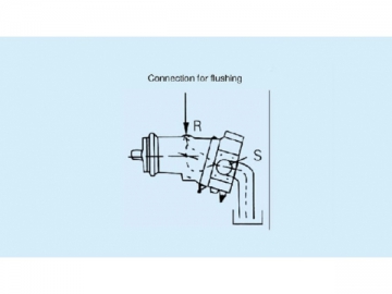
Flushing Fluid Port| Size | 20 | 40 | 58 | 78 | 117 |
| flow Qsp L/min | 2 | 4 | 6 | 8 | 12 |
Note: When the 0S7V bent axis piston pump is mounted on top of tank and works for a long time with zero stroke under 31.5MPa Pmax, a certain flow of flushing fluid that is equal to or more than the flushing flow as indicated for each size in the above table must be provided for flushing pump casing.
Temperature of flushing fluid: ≤tank temperature
By turning the handwheel, it enables the piston to move in an axial direction with the help of a screw, and moves the valve plate on its sliding plane via carrier pin, thus allowing the pump to change its displacement steplessly from Vgmin to Vgmax. The pump position indicator is located in the handwheel.
Manual controlPorts
B Pressure port
S Suction port
R Air bleed
| Size | a | A1 | A2 | A3 | A4 |
| 20 | 9° | 251 | 108 | 175 | 95 |
| 28 | 16° | 260 | 108 | 190 | 80 |
| 40 | 9° | 315 | 134 | 197 | 108 |
| 55 | 16° | 323 | 134 | 215 | 89 |
| 58 | 9° | 327 | 155.5 | 215 | 107 |
| 80 | 16° | 380 | 155.5 | 235 | 86 |
| 78 | 9° | 380 | 169 | 246 | 144 |
| 107 | 16° | 390 | 169 | 270 | 92 |
| 117 | 9° | 441 | 192 | 261 | 132 |
| 160 | 16° | 450 | 192 | 285 | 107 |
| Size | a | A1 | A2 | B1 | B2 |
| 20 | 9° | - | - | - | - |
| 28 | 16° | - | - | - | - |
| 40 | 9° | 317 | 100 | 175 | 132.5 |
| 58 | 9° | - | - | - | - |
| 80 | 16° | - | - | - | - |
| 78 | 9° | 315 | 1000 | 180 | 157.5 |
| 107 | 16° | 383 | 100 | 270.5 | 132.5 |
| 117 | 19° | - | - | - | - |
| 160 | 16° | 445 | 100 | 225 | 143 |
| 250 | 26.5° | 584 | 120 | 320 | 230 |
Please specify whether the handwheels are upwards or downwards when you order goods!


")


 Variable Displacement Axial Piston Pump/Bent Axis Pump/Axial Piston Motor/Bent Axis Motor, A6V
hydraulic-en.com
Variable Displacement Axial Piston Pump/Bent Axis Pump/Axial Piston Motor/Bent Axis Motor, A6V
hydraulic-en.com
 Replacement hydraulic pump for A7VO series 63 axial piston variable pump") K7VO K7VO (Replacement for A7VO Series 63) Replacement hydraulic pump for A7VO series 63 axial piston variable pump
hydraulicpump-motor.com
K7VO K7VO (Replacement for A7VO Series 63) Replacement hydraulic pump for A7VO series 63 axial piston variable pump
hydraulicpump-motor.com

 Replacement hydraulic motor for A6VE series 63&65&71 axial piston variable motor")
 Replacement hydraulic motor for A2FE axial piston fixed motor")


