Hydraulic Clamp System, FW-S Series
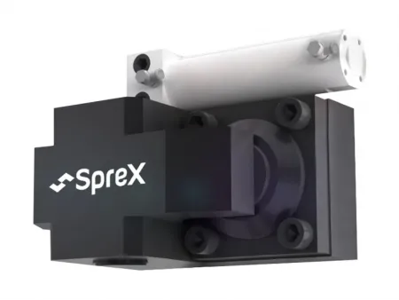
The FW-S series hydraulic clamping system is utilized for mold clamping work with an up-down clamping direction. It is equipped with an automatic movable cylinder, which can automatically clamp the mold with a manual pulling process, thus making operation more secure.
It is widely used for various mold processing equipment, including plastic injection molds, stamping dies, die casting molds, glass molds, rubber molds, metallurgy molds and more, and is a necessary piece of equipment for injection molding and die casting manufacturing.
- Clamping force (25MP): 20 kn
- Max. clamping stroke: 150 mm
- Driving air pressure: 0.4-0.55 mp
- Clamp moving speed: 30-80 mm/s (adjustable)
- Clamping force (25MP): 40 kn
- Max. clamping stroke: 150 mm
- Driving air pressure: 0.4-0.55 mp
- Clamp moving speed: 30-80 mm/s (adjustable)
- Clamping force (25MP): 60 kn
- Max. clamping stroke: 200 mm
- Driving air pressure: 0.4-0.55 mp
- Clamp moving speed: 30-80 mm/s (adjustable)
- Clamping force (25MP): 100 kn
- Max. clamping stroke: 300 mm
- Driving air pressure: 0.4-0.55 mp
- Clamp moving speed: 30-80 mm/s (adjustable)
- Clamping force (25MP): 250 kn
- Max. clamping stroke: 300 mm
- Driving air pressure: 0.4-0.55 mp
- Clamp moving speed: 30-80 mm/s (adjustable)
- Clamping force (25MP): 500 kn
- Max. clamping stroke: 300 mm
- Driving air pressure: 0.4-0.55 mp
- Clamp moving speed: 30-80 mm/s (adjustable)
Optional type
| Type | Clamping force(25MP) | Mix clamping stroke | Driving air pressure | Clamp moving speed | Weight |
| KN | mm | MP | mm/s | kg | |
| FW2-S | 20 | 150 | 4 | 30-80 Adjustable | 2 |
| FW4-S | 40 | 150 | 4 | 4.8 | |
| FW6-S | 60 | 200 | 4 | 7.2 | |
| FW10-S | 100 | 300 | 5 | 13 | |
| FW16-S | 160 | 300 | 5 | 23 | |
| FW25-S | 250 | 300 | 5 | 36 | |
| FW50-S | 500 | 300 | 5 | 80 |
Type selection
You can select the corresponding clamp type and number according to your equipment needs.
| Machine Capacity | Specs of the hydraulic clamping system | Thickness of mold platen(mm) | |||
| Fixed platen | Number | Movable platen | Number | ||
| 650-850 | FW16-S | 4 | FW16-S | 4 | 50 |
| 900-1300 | FW16-S | 6 | FW16-S | 6 | 50 |
| 1400-1600 | FW25-S | 6 | FW25-S | 6 | 50 |
| 1800-2800 | FW25-S | 8 | FW25-S | 8 | 60 |
| 3300-4000 | FW50-S | 8 | FW50-S | 8 | 60 |
| Specification | G | R | J | E | F | M | N | Rc | T | P | Q | K | L | H(Standard) |
| FW2 | 60 | 65 | 58 | 46.5 | 39.5 | 18 | 1/4 | 48 | M5X35 | 1/8 | 15 | 18 | 108.5 | 25 |
| FW4 | 66 | 72 | 80 | 54 | 47 | 18 | 1/4 | 70 | M5X35 | 1/8 | 15 | 23 | 108.5 | 30 |
| FW6 | 80 | 92 | 85 | 66 | 58 | 24 | 1/4 | 76 | M8X45 | 1/8 | 21 | 30 | 119 | 30 |
| FW10 | 90 | 110 | 109 | 75 | 66 | 32 | 1/4 | 95 | M10X55 | 1/8 | 26 | 30 | 137 | 40 |
| FW16 | 100 | 119 | 125 | 84 | 75 | 32 | 1/4 | 120 | M10X55 | 1/8 | 26 | 30 | 137 | 50 |
| FW25 | 113 | 150 | 150 | 97.5 | 95.5 | 41 | 1/4 | 135 | M12X70 | 1/4 | 32 | 30 | 163 | 50 |
| FW50 | 155 | 200 | 200 | 140 | 135 | 110 | 1/4 | 160 | M16X85 | 1/4 | 38 | 30 | 172 | 60 |
Note: H is the thickness of mold base plates that are paired with standard hydraulic clamps. Customization is available upon request.
- Advanced electrical system controller featuring an OMRON programmable controller, ensuring precise control and user-friendly operation interface.
- Multiple layers of safety protection, ensuring the safety of operators and preventing any potential hazards during the clamping process.


, ST Series")
")


")


")

")


