Waterflow Detector


General Info
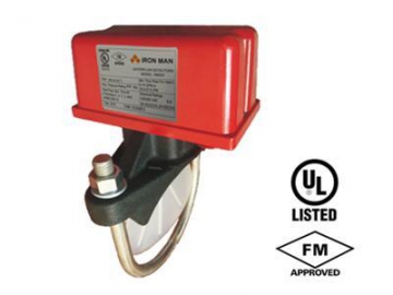
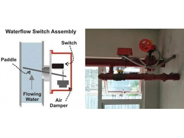
Waterflow detectors are mounted to water-filled pipes in sprinkler systems. It is used on steel pipe,schedules 10 through 40, sizes 50mm thru 200mm (2" thru 8"). Waterflow in the pipe deflects a vane, which triggers a switch usually after a specified delay period. All waterflow detectos have a pneumatically controlled mechanical delay mechanism. Delays reset if the flow of water stops before the entire delay has elapsed. All switches are actuate when the water flow rate is 10 gallons per minute or greater, but will not actuate if the rate is less than 4gallons per minute.
Our advantage
Designed for both indoor and outdoor use; temperature range 0° C to 49° C.
Equipped with tamper resistant screws to prevent unauthorized entry.
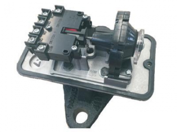
Two synchronized switches are enclosed in a durable terminal block. Terminals are easy to read and wire.
Built-In mechanical time delay feature; minimizing the risk of false alarms due to pressure surges or air trapped in the system.
The IM6001 offers excellent performance during riser vibrations caused by large in-rushes of water.
Designed and built for accuracy and repeatability.
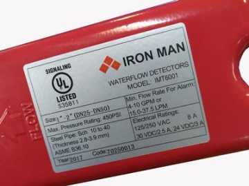
Specifications(IM6001)
Contact rating: 8A@250 VAC; 3A@24VDC;2.5A@30VDC
Flow sensitivity range: 4 to 10 GPM(15-38LPM)
Working pressure: 450PSI
Operating Temperature Range: 0℃ to 49℃
Corrosion Protection: Fusion bonded epoxy coated interior and exterior or enamel spray paint, interior and exterior
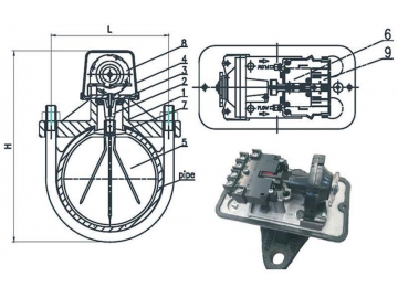
| Size | DN50 | DN65 | DN80 | DN100 | DN125 | DN150 | DN200 |
| L | 84 | 92 | 104 | 133 | 160 | 187 | 239 |
| H | 190 | 200 | 220 | 245 | 270 | 300 | 350 |
| Nominal Pipe OD. | 60.3 | 73 | 88.9 | 114.3 | 141.3 | 168.3 | 219.1 |
| Pipe Wall Thickness | 2.77-3.91 | 3.05-5.16 | 3.05-5.49 | 3.05-6.02 | 3.04-6.55 | 3.40-7.11 | 3.76-8.18 |
| No. | Part Name | Material |
| 1 | Saddle | DI,A536 65-45-12 |
| 2 | Holder | SS304 EPDM |
| 3 | Plate | Aluminum Alloy |
| 4 | Cover | Aluminum Alloy |
| 5 | Paddle | Plastic |
| 6 | Micro switch | Plastic |
| 7 | Gasket | EPDM |
| 8 | Retarding device | Plastic |
| 9 | Terminal Box | Plastic |
Retard Adjustment
The delay can be adjusted by rotating the retard adjustment knob from 0 to max setting. To adjust the setting, turn the adjustment knob clockwise to increase the delay, counterclockwise to decrease it. The time delay should be set at the minimum required to prevent false alarms.


")


")


