Get in touch with us
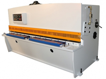
Hydraulic Swing Beam Shear


Request a Quote
Hydraulic swing beam shear has steel plate welded structure, hydraulic drive and accumulator return system, and is featured by reliable and smooth operation, small size, light weight and excellent rigidity.
Blade gap can be easily and rapidly adjusted. The shearing machine is equipped with back gauge and front gauge. The back gauge adopts mechanical transmission and digital display device, and it can be manually adjusted in an easy manner. The front gauge is equipped with ruler, positioning device and lighting unit to facilitate shearing operations, as well as front guarding to provide operators with guaranteed safety.
Features
- Machine Structure
Steel plate welded construction has an excellent rigidity. Two cylinders are mounted on both side columns. Worktable is configured with auxiliary blade holder to facilitate the slight adjustment of bottom blade holder. Besides, ball transfer unit on worktable enable material feeding easier. - Upper Blade Holder
With a robust steel plate welded structure, the upper blade moves in arc motion to provide high consistency of the blade gap during shearing process. - Hold Down Cylinder
Multiple hydraulic hold down cylinders are equipped with press pads. Through built-in spring, the press pad can be closely contacted with the material plate to provide sufficient pressure, then it will be reset by means of the tension of the spring when shearing process is completed. The pressing force of the hold down cylinder is varied according to various thickness of the material plate. - Front Gauge and Back Gauge
The front gauge is placed at worktable and equipped with ruler to assist in adjusting the gauge to required value, which significantly facilitates shearing operations
The back gauge is fixed on upper blade holder to move up and down along with upper blade holder. There is a hand wheel for operator to realize slight adjustment, providing a reliable adjusting operation.
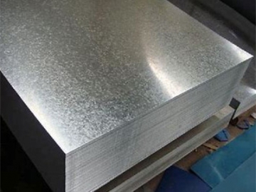
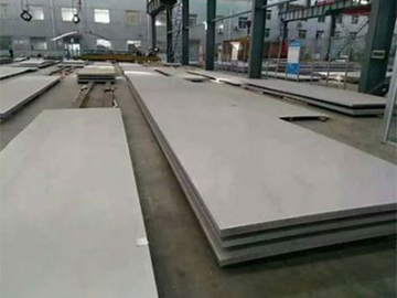
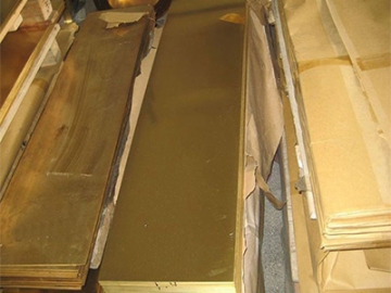
Applications
Details
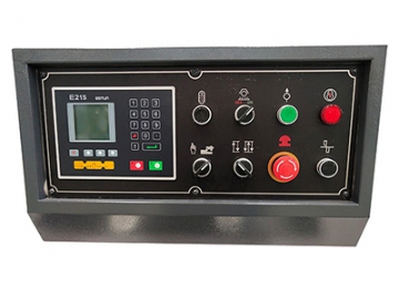
- E21S control system
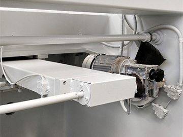
- Motorized back gauge
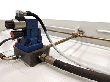
- Hydraulic system
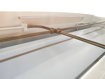
- Connector
Specifications
| No. | Model(QC12Y) | 4x1600 | 4x2000 | 4x2500 | 4x3200 | 6x2500 | 6x3200 | 8x2500 |
| 1 | Shearing thickness (mm) | 4 | 4 | 4 | 4 | 6 | 6 | 8 |
| 2 | Shearing width (mm) | 1600 | 2000 | 2500 | 3200 | 2500 | 3200 | 2500 |
| 3 | Cutting plate tensile strength N/mm3 | 450 | 450 | 450 | 450 | 450 | 450 | 450 |
| 4 | Shearing angle (°) | 1.5 | 1.5 | 1.5 | 1.5 | 1.5 | 1.5 | 1.5 |
| 5 | Back gauge range (mm) | 20-500 | 20-500 | 20-600 | 20-600 | 20-600 | 20-600 | 20-600 |
| 6 | Blade length (mm) | 1700 | 2100 | 2600 | 3300 | 2600 | 3300 | 2600 |
| 7 | Throat depth (mm) | 80 | 80 | 80 | 80 | 80 | 80 | 80 |
| 8 | Blade material | 6CrW2Si | 6CrW2Si | 6CrW2Si | 6CrW2Si | 6CrW2Si | 6CrW2Si | 6CrW2Si |
| 9 | Main motor power (KW) | 4 | 4 | 5.5 | 5.5 | 7.5 | 7.5 | 7.5 |
| 10 | Stroke (n/min) | 25 | 20 | 20 | 18 | 18 | 16 | 14 |
| 11 | Length (mm) | 2150 | 2560 | 3110 | 3748 | 3130 | 3748 | 3148 |
| 12 | Width (mm) | 1400 | 1400 | 1430 | 1675 | 1530 | 1675 | 1750 |
| 13 | Height (mm) | 1400 | 1450 | 1450 | 1600 | 1600 | 1620 | 1760 |
| No. | Model(QC12Y) | 8x3200 | 10x2500 | 10x3200 | 10x4000 | 12x2500 | 12x3200 |
| 1 | Shearing thickness (mm) | 8 | 10 | 10 | 10 | 12 | 12 |
| 2 | Shearing width (mm) | 3200 | 2500 | 3200 | 4000 | 2500 | 3200 |
| 3 | Cutting plate tensile strength N/mm3 | 450 | 450 | 450 | 450 | 450 | 450 |
| 4 | Shearing angle (°) | 1.5 | 1.5 | 1.5 | 1.5 | 2 | 2 |
| 5 | Back gauge range (mm) | 20-600 | 20-600 | 20-600 | 20-600 | 20-600 | 20-600 |
| 6 | Blade length (mm) | 3300 | 2600 | 3300 | 4100 | 2600 | 3300 |
| 7 | Throat depth (mm) | 80 | 80 | 80 | 80 | 80 | 80 |
| 8 | Blade material | 6CrW2Si | 6CrW2Si | 6CrW2Si | 6CrW2Si | 6CrW2Si | 6CrW2Si |
| 9 | Main motor power (KW) | 11 | 15 | 11 | 15 | 15 | 15 |
| 10 | Stroke (n/min) | 10 | 11 | 9 | 8 | 10 | 9 |
| 11 | Length (mm) | 3748 | 3200 | 3900 | 4760 | 3295 | 3925 |
| 12 | Width (mm) | 1800 | 1750 | 1800 | 2000 | 1800 | 1800 |
| 13 | Height (mm) | 1760 | 1760 | 1760 | 1760 | 1940 | 1940 |
Related products


Send Message
Other Products


Most Recent
")


")
More


Other Products


Videos


")