Laminated Busbar


Laminated copper bars for low-inductance power distribution in renewable energy, electric vehicles, rail, and industrial electrical systems
Laminated busbars are compact, multi-layer conductive assemblies used for distributing power efficiently in high-current electrical systems. Instead of relying on traditional wiring, they integrate copper layers and insulation into a single solid structure, reducing wiring complexity and improving electrical performance.
Each busbar is made by stacking alternating layers of copper conductors and insulating materials such as epoxy resin or polyimide film, which are then bonded through heat and pressure. This layered structure minimizes inductance and electrical noise while improving reliability and consistency. It also saves space and simplifies installation in systems where clean layouts and stable power delivery are essential. Thanks to their low impedance, strong thermal stability, and ability to handle high current loads, laminated busbars are widely used in renewable energy systems, electric vehicles, rail transit, power inverters, and industrial automation.
- Laminated busbars have a thin layered design with a broad heat dissipation surface and low impedance characteristics, which help reduce temperature rise and improve cooling efficiency. By sealing the edges through a hot-press process, laminated busbars gain higher strength and better heat resistance, allowing them to perform reliably over long periods.
- Compared with cables of the same size, laminated busbars can carry more current and transmit power more efficiently. They handle up to 3300 V and 1200 A, making them suitable for high-power industrial systems.
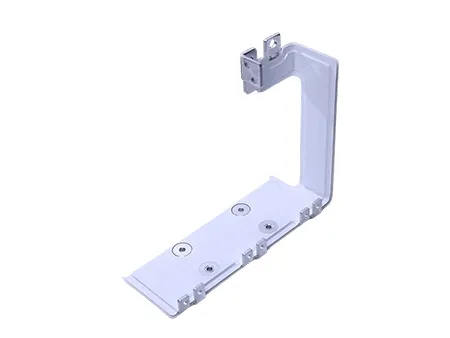
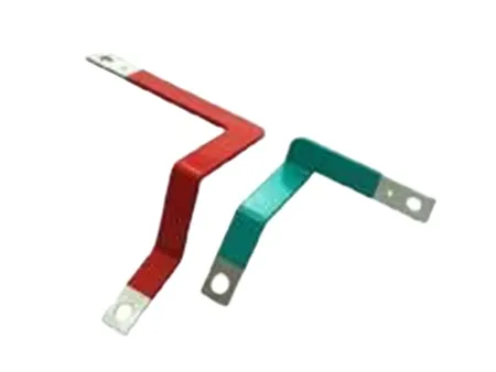
- Can be customized into various shapes, including L- and U-type bends, to simplify internal wiring and make better use of space inside electrical equipment.
- The flat conductor arrangement minimizes electromagnetic interference and improves system stability, making these busbars ideal for applications with strict EMC requirements, including inverters and converters.
- The flat, multi-layer structure of the laminated busbars, combined with low-dielectric insulation materials, keeps stray inductance and impedance low. This design minimizes transmission losses, reduces voltage spikes and electromagnetic interference during switching, and improves overall system stability.
- The rigid multi-layer compact structure saves installation space and withstands harsh conditions such as high temperature and vibration, suitable for high-density applications in renewable energy systems, rail transit, and heavy-duty equipment.
- Using standardized connection points and a hot-press forming process helps the laminated busbars fit neatly into the equipment layout. This makes installation faster and more accurate, reduces wiring work and overall costs, and leaves room for later adjustments or upgrades.
| Product type | Laminated Busbar | ||||||||
| Conductor material | T2 copper/1060 aluminum/copper-clad aluminum Other materials are customizable upon request | ||||||||
| Insulation voltage | 300V–20kV | ||||||||
| Max. withstand voltage | 1000V–20kV | ||||||||
| Rated current | 0–4000A | ||||||||
| Connection method | Copper plate press-fit Copper bar bolted Copper bar welded | ||||||||
| Surface treatment | Tin plating, nickel plating, conductive oxidation, or anodizing Other surface treatments are customizable upon request | ||||||||
| Interlayer adhesion strength | > 1300N (peel strength between laminated layers) | ||||||||
| Insulation material | NOMEX, PVF, PET, PI, FR4, insulation powder, GPO3 Other materials are customizable upon request | ||||||||
| Partial discharge | |||||||||
| Parasitic inductance | 15nH/m | ||||||||
| Flame retardant rating | UL 94V-0 | ||||||||
| Insulation resistance | ≥20MΩ, DC/1000V | ||||||||
| Temperature rise | ≤30K | ||||||||
| Max. number of layer | 6 layers | ||||||||
| Max. dimensions | 1000×1800mm (dimensions within this range customizable upon request) | ||||||||
| Operating temperature | -40℃ to 105℃ | ||||||||
| Production capacity | 20000 pcs/month | ||||||||
| Delivery cycle | 2–3 weeks (batch production: 3 weeks per 100 pcs, additional quantities as scheduled per contract) | ||||||||
| Insulation material | Material properties | Density (g/cm³) | Thermal expansion coefficient | Thermal conductivity (W/kg.K) | Dielectric constant (f=60 Hz) | Dielectric strength (kV/mm) | Flame retardant rating | Heat resistance (°C) | Water absorption (%)/24h |
| NOMEX | 0.8–1.1 | - | 0.143 | 1.2 | 9 | 94, V-0 | 220 | - | |
| PI | 1.42 | 20 | 0.094 | 3.7 | 9 | 94, V-0 | 220 | 0.24 | |
| PVF | 1.38 | 53 | 0.126 | 10.4 | 19.7 | 94, V-0 | 105 | 0 | |
| PET | 1.38–1.41 | 60 | 0.128 | 3.3 | 25.6 | 94, V-0 | 120 | 0.1–0.2 | |
| FR4 | 1.32 | 45–65 | 0.18 | 4.4 | 15.7 | 94, V-0 | 155 | 0.1–0.2 | |
Injection-molded busbars are a newer type of busbar made to handle higher power levels without increasing the conductor size. They use advanced insulation and molding techniques that let them withstand higher temperatures, up to 125 °C, while keeping performance stable and reliable in demanding conditions.
Compared with other composite types, such as ROLINX Easy & Performance busbars, which typically operate at around 105 °C, this higher temperature rating gives them a clear advantage in high-power designs. Their enhanced insulation also enables long-term performance under extreme humidity conditions, such as 85 °C and 95% RH, far beyond the standard 55 °C and 95% RH operating limits. Injection-molded busbars are commonly used in equipment that runs on high power for long periods, such as industrial inverters, renewable energy converters, and heavy-duty traction systems found in trains, ships, and mining vehicles.
| Product type | Injection-Molded Busbar |
| Voltage | 12kV, DC |
| Power rating | Kilowatt/Megawatt |
| Operating temperature | -50℃ to 125℃ |
| Relative humidity | 95%RH@55℃ (standard) 95%RH@85℃ (upgraded) |
| Conductor material | Copper/aluminum |
| Insulation material | Polyester dielectric film, rigid insulation board |
| Related tests | Partial discharge, high voltage and dimensional tests |
- Frequency Converters
- Wind and Photovoltaic Power Systems
- Railway Transportation Systems
- Automotive Industry
What type of power distribution component can replace traditional copper busbars in wind and solar power systems where large current transmission causes energy loss and space limitations?
In these cases, laminated busbars are a more efficient choice. Their layered copper and insulation structure makes the current flow path shorter, which helps reduce power loss by more than 30% compared with traditional copper bars. They also take up much less space, making them a good fit for compact installations like inverters and combiner boxes. The multi-layer design also minimizes electromagnetic interference, helping the system run smoothly even under high current conditions.
2.Why do laminated busbars have lower transmission losses compared with traditional copper bars, and what other benefits do they offer in high-power systems?
Laminated busbars are built with several layers of insulated copper foils arranged in parallel, which keeps the current path short and direct. This design lowers parasitic inductance and resistance by around 30–50%, helping reduce heat generation and energy loss. They’re also about half the size of traditional copper bars, making them ideal for compact equipment layouts. The layered structure improves heat dissipation and minimizes electromagnetic interference from high current, which helps protect nearby components and ensures stable operation in high-power systems such as wind inverters and energy storage PCS units.