Counterflow Cooling Tower (Steel Closed Circuit Cooling Tower)

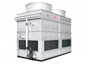

The steel closed circuit cooling tower utilizes a counterflow method, as air enters the cooling tower from the bottom louvers. It is designed with a closed circuit structure with a number of advantages. Water will not evaporate, and there is an extremely low concentration of calcium and magnesium ions, thus no impurities such as calcium carbonate or magnesium carbonate are formed. This also prevents scaling problems that are often generated during cooling tower operation, and thus, saves overall maintenance expenses and extends the service life.
Water, oil or other liquid flows in a circular manner inside the curved pipes, through which the heated fluid spreads into the water on the pipe surface. Air outside the unit enters from the air inlet screen at the bottom of the tower and directly opposite the main water flow. A small amount of water evaporates and absorbs heat, and the hot, wet air is released into the atmosphere via the exhaust fan at the top of the tower. The remaining water falls into the bottom basin, is recycled, then transported via a pump to the water distribution system, where it will be sprinkled on the pipes again.
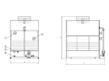
All the following dimensions are referenced to evaporative cooling products, and we also offer customization services according to customer requirements.
1. Water inlet
2. Water outlet
3. Water filler pipe
4. Overflow pipe
5. Drain pipe
- Inlet water temperature: T1=37℃
- Outlet water temperature: T2=32℃
- Wet bulb temperature: TWB=28℃
- Dry bulb temperature: T=31.5℃
- Atmospheric pressure: P=99.4KPa
| Model | Overall dimension (mm) | Approximate weight (Kg) | Fan power | Pump power | Inlet/outlet pipe diameter | ||||
| L | W | H | Heaviest part | Transporting | Running | (KW) | (KW) | (mm) | |
| LYN-5 | 1260 | 990 | 2000 | 278 | 360 | 576 | 1.1 | 0.55 | 32 |
| LYN-8 | 1260 | 990 | 2000 | 326 | 410 | 656 | 1.1 | 0.55 | 32 |
| LYN-15 | 2010 | 1200 | 2000 | 543 | 685 | 1109 | 1.5 | 0.75 | 50 |
| LYN-25 | 2010 | 1200 | 2000 | 712 | 890 | 1420 | 1.5 | 0.75 | 50 |
| LYN-30 | 2500 | 1200 | 2000 | 805 | 995 | 1611 | 2.2 | 1.1 | 65 |
| LYN-40 | 2500 | 1200 | 2000 | 928 | 1160 | 1879 | 2.2 | 1.1 | 80 |
| LYN-50 | 2500 | 1200 | 2000 | 1020 | 1275 | 2040 | 3 | 1.5 | 80 |
| LYN-60 | 2500 | 1510 | 2600 | 1160 | 1450 | 2320 | 2.2*2 | 1.5 | 100 |
Note: the above data belongs to copper heating pipe and its material should be determined by the property of fluid.
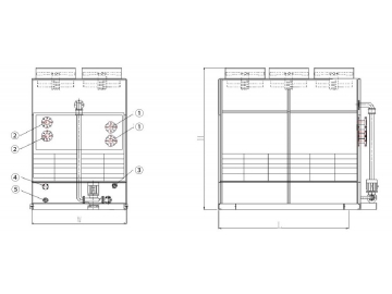
1. Water inlet
2. Water outlet
3. Water filler pipe
4. Overflow pipe
5. Drain pipe
- Inlet water temperature: T1=37℃
- Outlet water temperature: T2=32℃
- Wet bulb temperature: TWB=28℃
- Dry bulb temperature: T=31.5℃
- Atmospheric pressure: P=99.4KPa
| Model | Overall dimension (mm) | Approximate weight (Kg) | Fan power | Pump power | Inlet/outlet pipe diameter | ||||
| L | W | H | Heaviest part | Transporting | Running | (KW) | (KW) | (mm) | |
| LYN-70 | 2500 | 1510 | 2600 | 1377 | 1700 | 2737 | 2.2*2 | 2.2 | 100 |
| LYN-80 | 2500 | 1510 | 2600 | 1560 | 1950 | 3120 | 2.2*2 | 2.2 | 100 |
| LYN-100 | 3000 | 1510 | 3000 | 2162 | 2700 | 4370 | 3*2 | 3 | 125 |
| LYN-125 | 3000 | 1510 | 3000 | 2568 | 3270 | 5136 | 3*2 | 3 | 150 |
| LYN-175 | 3910 | 2000 | 3560 | 3321 | 4100 | 6642 | 4*3 | 4.4 | 250 |
| LYN-200 | 3910 | 2210 | 3600 | 3688 | 4610 | 7422 | 4*3 | 4.4 | 80*8 |
| LYN-250 | 4300 | 2520 | 3600 | 4712 | 5890 | 9420 | 4*4 | 6 | 100*8 |
| LYN-275 | 4300 | 2520 | 3600 | 5200 | 6500 | 10400 | 4*4 | 6 | 80*16 |
Note: the above data applies to copper heating pipe of which the material should be determined depending on the property of fluid.
")
")

")


