Agitation Tank

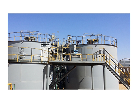
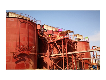
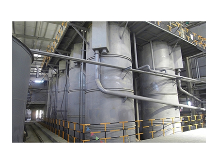

The cyanidation leaching agitation tank is used for gold and silver leaching and carbon absorption in metallurgical, chemical and light industries.
This leaching tank consists of a circular cell and an agitator that contains an upper and a lower impeller which have four blades individually. The agitator is driven by a system combining a motor, a speed reducer, and a bracket. The force produced by the rotating impellers pushes the ore slurry to the cell's bottom, where the slurry flows outward in a radial manner. Then, the slurry flows upward along the baffles, creating a closed l. If the machine serves as a leach tank, the lixiviant and air will be added in the tank (reaction vessel). Gold will then be leached out of the gold cyanide complex. If the machine serves as a absorption tank, activated carbon will be added to absorb the gold from the dissolved solution.
In order to recover as much gold as possible, usually six agitation tanks work simultaneously.
- Supporting steady flows and even mixing whilst requiring the minimum power consumption from the drive;
- Dispersing the air evenly, making the best of the oxygen;
- Able to avoid deposits due to the unique design of the agitator;
- Rubber impeller blades running at low rotating speeds and with a long service life that can protect the activated carbon and minimize the carbon loss, in which case no carbon loaded with gold will enter the tailings;
- The air inflation system decreases waste in oxygen consumption, enabling the full contact among oxygen, reagent, and ore slurry, which boosts the leaching efficiency and shortens the leaching time;
- The air inflation device and the high-pressure water device share a pipe system, making it easy to start the agitator. If the tank full of ore slurry is off for a long time, the mineral particles will sink and be stacked in heaps on the bottom, until the height of the heap surpasses the lower impeller. The impeller will remain locked before the particles around are removed by the high-pressure water poured in.
| Model | Tank Spec. Diameter × Height (mm) | Effective Volume(m3) | Impeller Rotation Speed (r.p.m) | Impeller Diameter (mm) | Power (kW) |
LT2.0×2.5 | 2000×2500 | 6 | 52 | 909 | 2.2 |
LT2.5×3.15 | 2500×3150 | 13.14 | 935 | ||
LT3.0×3.15 | 3000×3150 | 18.93 | 43 | 1130 | 4 |
LT3.0×3.5 | 3000×3500 | 21 | |||
LT3.15×3.55 | 3150×3550 | 24 | 1260 | ||
LT3.5×3.5 | 3500×3500 | 30 | 52 | 1310 | 5.5 |
| Model | Tank Spec. Diameter × Height (mm) | Effective Volume (m3) | Impeller Rotation Speed (r.p.m) | Impeller Diameter (mm) | Power (kW) |
LT4.0×4.5 | 4000×4500 | 48 | 35 | 1750 | 7.5 |
LT4.5×5.0 | 4500×5000 | 71.57 | 1750 | ||
LT5.0×5.6 | 5000×5600 | 98 | 31 | 2046 | 11 |
LT5.5×6.0 | 5500×6000 | 112 | 2100 | ||
LT6.5×7.0 | 6500×7000 | 195 | 21 | 2400 | 22 |
LT7.0×7.5 | 7000×7500 | 245.4 | 21 | 2400 | 22 |
LT7.5×8.0 | 7500×8000 | 268.6 | 23 | 2900 | 22 |
LT8.0×8.5 | 8000×8500 | 342 | 18.5 | 3300 | 30 |
| Model | Tank Spec. Diameter × Height(mm) | Effective Volume (m3) | Impeller Rotation Speed (r.p.m) | Impeller Diameter (mm) | Power (kW) |
LT8.5×9.0 | 8500×9000 | 435 | 18.5 | 3436 | 30 |
LT9.0×9.5 | 9000×9500 | 515 | 14.8 | 3900 | 37 |
LT9.5×10 | 9500×10000 | 638 | 14.8 | 4000 | 45 |
LT10×10.5 | 10000×10500 | 705 | 14.8 | 4000 | 45 |
LT10.5×11 | 10500×11000 | 815 | 13.2 | 4400 | 55 |
LT11×12 | 11000×12000 | 983 | 13.2 | 4400 | 55 |
LT12×13 | 12000×13000 | 1320 | 12 | 4800 | 75 |


")


