Portal Frame Introduction

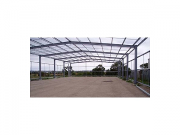


Portal frame steel clad structure is the most common type of industrial buildings. It consists of a series of parallel portal frames as the major framing elements. Each frame is rigid, and resists horizontal wind forces in the plane of the frame by flexural action. It is widely used for framing of single storey buildings. Compared with truss system, portal frames have low structural height and clean appearance. It is also easy for coating maintenance.
Due to the prefabrication of steel members, portal frames can be quickly installed, saving money, time, and labor. Its versatility allows designs to be as simple or as complicated as required. The base connection, the knee joint, and the apex are three basic factors of portal frame structure.
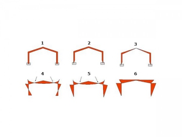
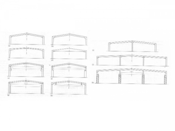
Types of portal frames
1. Constant cross section
2. Tapered members
3. Portal with crane runway brackets
4. Separate crane posts
5. Rafter hung crane runway (2 pictures)
6. Multiple columns
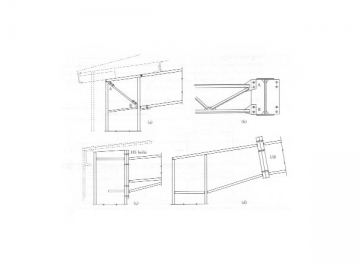
Figure 10.16 Types of portal frames for industrial buildings : (a ) constant cross-section;(b) to (d)Tapered members;(e) portal with crane runway brackets;(f)stepped column portal ;(g) separate crane past; (h) rafter hung crane runways;(i) to (k)multiple column.
Framing systems
Portal frames gain resistance to vertical and lateral loads through frame action.
1. RIGID BASE, 2. 2 PIN, 3. 3 PIN , 4. Contra flexure, 5. Contra flexure, 6. No Contra flexure
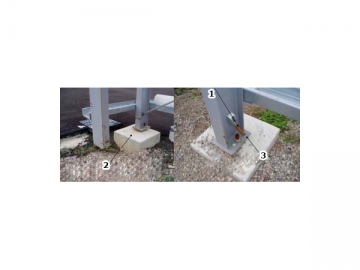
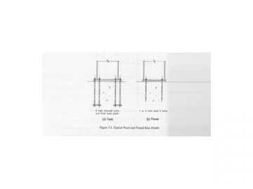
Rigid base
1. Rigid frame base preparation, 2. Rigid frame base column attachments
1. Rigid Base, 2. BM transferred through rigid base connection to footing system
A rigid base portal frame is generally characterized by a lighter frame, but subsequently heavier footings. With induced bending at the apex, knee and base, the direction of the bending moment changes at the point of contra flexure equaling zero.
Rigid base connections space bolts as far away from the centre line of the columns as possible. The purpose is to transfer the bending moments away through the joint. A rigid base carries the bending moment and axial loads through to the footing system, which then reduces the bending moment throughout the frame. Rigid base frames are used predominately on poor foundations. However, when they are used, the structural action is enhanced because all members are then fully utilized.
Pin portal Frames
1. 2 Bolt-Pin base connection, 2. Pin Portal Frame Joint & Footing, 3. Bracing connection
Pinned base frame, frames with flexible connection to the footings, derive their resistance to lateral forces from their rigid knee action. This type of framing is commonly used for buildings with relatively low span to column height. The main advantage is in low footing cost, because the footings do not need to resist very large bending moments.
2 pin portal
1. Rigid connection at apex, 2. Pin, 3. Pin
Maximum bending occurs at the apex and at the knees because both elements are rigid. There is zero bending moments at the base and at points of contra flexure. The only pin connections are at the bases of columns.
3 pin portal
1. Rigid connection at apex, 2. Pin, 3. Pin
There is a pin connection at the apex and at the base footings. The advantage of the 3 pin portal is that it does not transfer bending moments to the footing or to the apex. The knees are the only rigid element in this design, and hence here it has the maximum bending moments applied under load. There are no contra flexure points for a 3 pin portal structure.
Function
Large clear spans of up to about 40 meters can be achieved economically using universal beams (UB) or welded beam (WB) rafters.
The understanding of the frame under load and an awareness of the points of high stress are important factors in portal frame design. Generally, the portal frame is designed with a low pitched roof, then the frame minimizes stress throughout the knees, and hence through to the base and foundations.
The design takes a limit state approach. It encompasses the prevailing loads which will act upon the frame, and the required members which will maintain minimal movement by counteracting these loads.
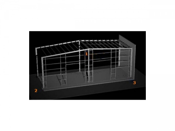
Construction
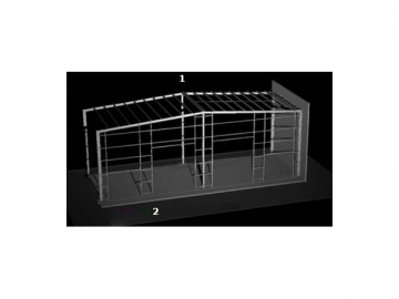
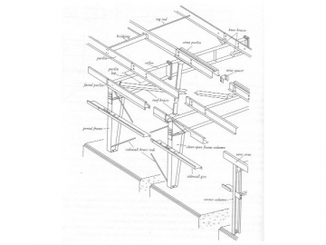
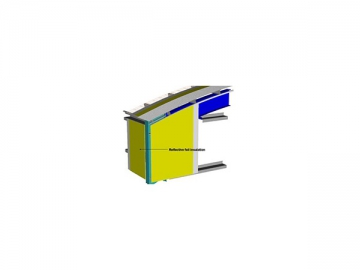
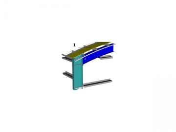
Components of a typical portal frame
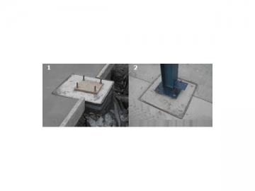
Footing details
Stanchion/column
Stanchion/ column
Mild steel Universal Beam (not usually UC)
Compression members are always loaded by combined compression and bending. The bending moments may arise from the eccentric application of the load or from the overall frame action. The compression capacity for a member is reduced in the presence of bending moments.
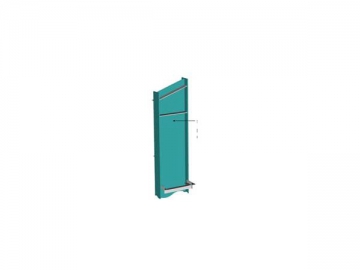
Rafters/ beams
Web Stiffeners
The main function of the web is to resist shear forces arising from the variation of the bending moment along the span. The web also serves to receive the bearing reaction and disperse into itself.
1. Diagonal cross bracing 20mm diarod
2. Adjustment for bracing
1. Purling Z,C section, cold formed note direction
2. Girts Z,C section ,cold formed
Purlins provide lateral but not rotational restraint to the outside flange. Purlins are generally made from cold formed steel sections which are lightweight and easily fixed.
Safety Mesh 1. Safety mash for working on roof
The safety mesh must be correctly fixed before any roof cladding work can begin. The mesh prevents workers from falling during the installation stage.
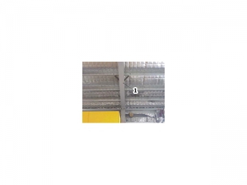
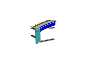
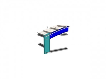
Structural bracing/fly bracing 1. FLY BRACING
Under uplift, most of the bottom flange of a portal frame rafter is in compression. In such cases, the rafter is attached to the purlin at the tension flange level, and the compression flange of the rafter is unrestrained. In order to achieve increased member capacity, the usual way is to laterally restrain the bottom flange of the rafter by providing fly bracing using small angle section members joining the bottom flange to the purlins.
- Waterproofing Sarking and insulation as req'd
- Roof cladding Roofing tray or corrugated
- Wall Insulation
Floor systems
The reinforced concrete floor slab is most common to portal frame structural systems. The advantages are that it has good load carrying resistance, suppression of noise, and an even surface for rolling loads. The disadvantages are: high unit weight, difficulties in making alterations, and relatively high cost.
Another portal frame flooring option is the composite reinforced concrete slab, which is the same as the reinforced concrete but with the additional advantage of economy offered by the composite action with steel beams and the facility of providing full lateral bracing to the beams.
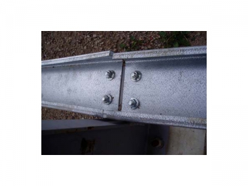
Connections
Connections play a prominent part in the economy of steel work. The making of connections and details are a labor-intensive process because many small pieces have to be manufactured and fitted within tolerances specified. The following principles need to be kept in mind:
1. They need to be deigned for strength:
a. Direct force transfer path
b. Avoidance of stress concentration
c. Adequate capacity to transfer the forces involved
2. Designed for fatigue resistance:
a. avoidance of notches
b. careful design of welded joints
3. Designed for serviceability:
a. Avoidance of features that can cause collection of water
b. Ease of application of protective coatings
c. Absence of yielding under working load
4. Designed for economy:
a. Simplicity
b. Minimum number of elements in the connection
c. Reducing the number of members meeting at the connection
HS bults
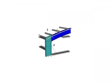
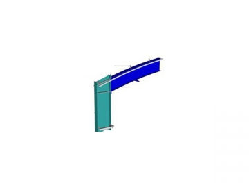
Figure 10.17
Portal frame knee connections:(a) field welded connections:(b) lateral bracing A-B;(c)bolted connection ;(d) stub connection.
Durability
The designer must ensure that the structure behaves as expected, and can perform its intended function at service loads. The most important limit states to consider for a portal frame building are those of limiting excessive deflection, and preventing excessive vibration.
Problematic excessive deflection basically becomes the root of all imaginable industrial building serviceability problems, including:
1. Damage to cladding and fixings affecting hold down capacity of fixings and water tightness
2. Ponding of water on low pitched roofs and possible leakage because of ponding or insufficient pitch
3. Visually objectionable sag in rafters or in suspended ceilings whose ceiling hangars are difficult to adjust for sag, e.g. heavy acoustic ceilings
4. Disturbing roof movements underfoot during maintenance
5. Noticeable and disturbing movement under wind load including possible creaks and groans
6. Damage to fixings between suspended ceilings and walls under uplift, and possible collapse of internal walls following loss of support from the ceiling
7. Danger to operation of monorail cranes suspended from the rafters
8. Danger to operation of gantry cranes through excessive lateral deflection or spread of columns
Although vibration and subsequently deflection are problematic in steel structures, it would be a highly suitable for buildings required to be earthquake resistant. This is because the steel members and components possess inherent ductility and a high ratio of strength to weight. Again, emphasis and quality workmanship lies in the detailing of the connections, so that ductility is translated through from the smallest component to the primary members.
Other precautions should also be taken into consideration to maximize serviceability, such as fire protecting members, and applying corrosion protection, i.e. galvanizing.
Material Steel portal frames are very efficient in material use, without compensating on structural integrity and are therefore competitive in price.
Rolled universal sections are utilized for the columns and rafters for the frames, which are usually designed by elastic analysis.
In the design of the rafters and columns in portal frames, the selection of the member sizes may be decided by the ultimate or strength limit state or by limiting deflections in the serviceability limit state. Axial and bending capacities are obtained through a consideration of flexural-torsional buckling of each member respectively.
As a material, steel has its characteristics: superior quality, versatility with off-site production, versatility with on-site construction, prefabrication potential, accuracy and integration with engineered computations, and immediate loading (strength) of structure.


mm×2200mm Slitting Line")


")


")


