Cooling Tower


Heat Rejection Unit for Industrial Cooling Water Systems
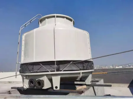
Cooling towers serve as efficient heat exchange systems that lower water temperature through the principle of evaporative cooling. They function by transferring waste heat from circulating cooling water into the atmosphere, effectively dissipating thermal load from industrial processes.
The tower housing is constructed from polyester fiberglass, delivering a combination of light weight, high strength, corrosion resistance, and long-term durability. The fan cylinder incorporates an energy recovery design to optimize airflow distribution and enhance operational efficiency. Additionally, the fan blades are made of airfoil-shaped epoxy fiberglass, ensuring high air delivery, improved energy efficiency, reduced noise levels, and reliable corrosion resistance.
Together, these features enable consistent and economical heat rejection, supporting stable operation across a wide range of industrial applications.
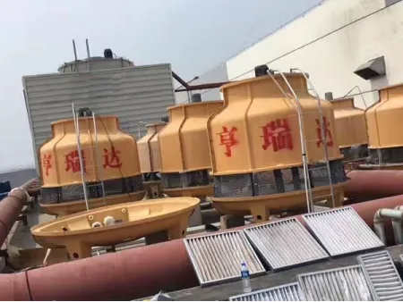
Cooling towers are widely used across various sectors for efficient heat rejection and water conservation. Their primary applications include:
- HVAC&R Systems Large-scale air conditioning, refrigeration plants, cold storage facilities, freezing systems, and combined heating and cooling installations.
- Manufacturing & Process Industries Plastics, rubber, chemical and petrochemical production, metal casting, steel manufacturing, food and pharmaceutical processing, and textile operations.
- Mechanical Equipment Cooling Generators, steam turbines, air compressors, hydraulic systems, and industrial engines.
- Other Industrial & Commercial Uses Additional cooling applications in sectors such as leather tanning, foam manufacturing, aluminum profile production, and specialized industrial water cooling.
| Model (HTCT-***) | Ton | | | | | | | | | | | | | | |
| General | Flow rate | m³/h | 6.23 | 7.8 | 11.7 | 15.6 | 19.5 | 23.4 | 31.2 | 39.2 | 46.8 | 62.4 | 78.1 | 97.5 | 117 |
| Air flow | cmm | 70 | 85 | 140 | 160 | 200 | 230 | 280 | 330 | 420 | 450 | 700 | 830 | 950 | |
| Fan motor | kW | 0.18 | 0.18 | 0.18 | 0.37 | 0.55 | 0.55 | 0.75 | 1.5 | 1.5 | 1.5 | 2.2 | 2.2 | 2.2 | |
| Drive | Direct drive | ||||||||||||||
| Noise level (16m) | dBA | 45.5 | 62.5 | 62.5 | 63 | 63 | 63 | 63 | 63.5 | 63.5 | 64 | 64.5 | 655 | 95 | |
| Net weight | kg | 42 | 50 | 54 | 67 | 98 | 116 | 130 | 200 | 250 | 280 | 450 | 540 | 580 | |
| Running weight | kg | 180 | 190 | 290 | 300 | 500 | 530 | 55d | 979 | 1250 | 1280 | 1650 | 1740 | 1780 | |
| Piping | Water inlet | mm | 40 | 40 | 50. | 50 | 80 | 80 | 80 | 80 | 100 | 100 | 125 | 125 | 150 |
| Water outlet | mm | 40 | 40 | 50 | 50 | 80 | 80 | 80 | 80 | 100 | 100 | 125 | 125 | 150 | |
| Overflow | mm | 25 | 25 | 25 | 25 | 25 | 25 | 25 | 25 | 25 | 25 | 25 | 25 | 25 | |
| Drain | mm | 25 | 25 | 25 | 25 | 25 | 25 | 25 | 25 | 25 | 25 | 25 | 29 | 25 | |
| Height | Flow valve | mm | 15 | 15 | 15 | 15 | 15 | 15 | 15 | 15 | 20 | 20 | 20 | 20 | 20 |
| Tower body | mm | 1650 | 1650 | 1750 | 1770 | 1870 | 1870 | 1980 | 2020 | 2150 | 2260 | 2400 | 2400 | 2550 | |
| Cell | mm | 940 | 1070 | 859 | 1140 | 1385 | 1130 | 1255 | 1255 | 1290 | 1455 | 1595 | 1780 | 1720 | |
| Air inlet | mm | 170 | 170 | 170 | 170 | 245 | 245 | 245 | 245 | 325 | 325 | 325 | 325 | 325 | |
| Water basin | mm | 420 | 420 | 450 | 450 | 450 | 340 | 340 | 420 | 460 | 460 | 450 | 450 | 450 | |
| Water inlet | mm | 270 | 270 | 280 | 175 | 175 | 175 | 175 | 230 | 295 | 295 | 300 | 300 | 300 | |
| Water outlet | mm mm | 180 | 180 | 190 | 190 | 115 | 115 | 115 | 125 | 200 | 200 | 230 | 230 | 230 | |
| Foundation | mm | 250 | 250 | 250 | 250 | 300 | 300 | 300 | 300 | 300 | 300 | 300 | 300 | 300 | |
| Diameter | Fan | mm | 550 | 600 | 600 | 600 | 770 | 770 | 770 | 930 | 1170 | 1170 | 1450 | 1450 | 1450 |
| Water basin | mm | 920 | 1060 | 1060 | 1170 | 1400 | 1650 | 1650 | 1830 | 2100 | 2100 | 2700 | 2700 | 3000 | |
| Foundation | mm | 554 | 554 | 797 | 797 | 1016 | 1016 | 1170 | 1170 | 1600 | 1600 | 2495 | 2495 | 2495 | |
| Screw | mm | 9×3 | 9×3 | 9×3 | 9×3 | 9×3 | 9×4 | 9×4 | 9×4 | 11×4 | 11×4 | 11×6 | 11×6 | 11×6 | |
| Material | Fan | Fiberglass reinforced polyester (FRP)/aluminum alloy | |||||||||||||
| Fan guard | —— | Galvanized steel | |||||||||||||
| Motor | TEFC-type motor 380V/50HZ 3Ph | ||||||||||||||
| Motor support | Galvanized steel | ||||||||||||||
| Casing | Fiberglass reinforced polyester (FRP) | ||||||||||||||
| Water basin | |||||||||||||||
| Sprinkler system | Polycarbonate & PVC pipe | Aluminum alloy/PVC pipe | |||||||||||||
| Eliminator | Fiberglass reinforced polyester (FRP) | ||||||||||||||
| Tension bar | Galvanized steel | ||||||||||||||
| Air inlet support | Polycarbonate & PVC pipe | Aluminum alloy/PVC pipe | |||||||||||||
| Tower support | |||||||||||||||
| Ladder | Galvanized steel | ||||||||||||||
| Piping | PVC pipe | ||||||||||||||
| Infill support | Polycarbonate | Polycarbonate & galvanized steel | |||||||||||||
| Infill | PVC film | ||||||||||||||
Design conditions: Inlet water temperature (T₁) = 37°C, outlet water temperature (T₂) = 32°C, wet bulb temperature (WBT) = 27°C, water temperature drop (ΔTₛ) = 5°C, atmospheric pressure (P) = 99,400 Pa.
| Model (HTCT-***) | Ton | | | | | | | | | | | | | |
| General | Flow rate | m³/h | 136.8 | 156.2 | 175.5 | 195.1 | 234 | 273.2 | 312.1 | 392.4 | 468 | 547.2 | 626.4 | 781.2 |
| Air flow | cmm | 1150 | 1250 | 1500 | 1750 | 2000 | 2200 | 2400 | 2600 | 3750 | 3750 | 5000 | 5400 | |
| Fan motor | kW | 4 | 4 | 5.5 | 5.5 | 7.5 | 7.5 | 11 | 11 | 15 | 18.5 | 22 | 22 | |
| Drive | Direct drive | Y-belt | Gearbox | |||||||||||
| Noise level (16m) | dba | 66 | 66 | 665 | 67 | 67.5 | 68 | 68 | 68.5 | 68.5 | 69 | 70 | 70.5 | |
| Net weight | kg | 760 | 780 | 1050 | 1080 | 1760 | 1800 | 2840 | 2900 | 3950 | 4050 | 4700 | 4900 | |
| Running weight | kg | 1860 | 1880 | 2770 | 2800 | 3790 | 3930 | 5740 | 5800 | 9350 | 9450 | 11900 | 12100 | |
| Piping | Water inlet | mm | 150 | 150 | 200 | 200 | 200 | 200 | 200 | 250 | 250 | 250 | 300 | 300 |
| Water outlet | mm | 150 | 150 | 200 | 200 | 200 | 200 | 200 | 250 | 250 | 250 | 300 | 300 | |
| Overflow | mm | 25 | 25 | 80 | 80 | 80 | 80 | 80 | 80 | 100 | 100 | 100 | 100 | |
| Drain | mm | 25 | 25 | B0 | B0 | 80 | 80 | 80 | 80 | 100 | 100 | 100 | 100 | |
| Height | Flow valve | mm | 20 | 20 | 25 | 25 | 25 | 25 | 40 | 40 | 50 | 50 | 50 | 50 |
| Tower body | mm | 2750 | 2750 | 3620 | 3620 | 3680 | 3680 | 4070 | 4070 | 4560 | 4560 | 4720 | 4720 | |
| Cell | mm | 1965 | 1965 | 2060 | 2060 | 2160 620 900 | 2160 | 2180 | 2180 | 2430 | 2630 | 2630 | 2630 | |
| Air inlet | mm | 350 | 350 | 620 | 620 | 620 | 620 | 620 | 760 | 1020 | 1020 | 1020 | 1020 | |
| Water basin | mm | 850 | 850 | 900 | 900 | 900 | 900 | 900 | 900 | 1020 | 1020 | 1020 | 1020 | |
| Water inlet | mm | 245 | 245 | 280 | 280 | 280 | 280 | 280 | 280 | 340 | 340 | 340 | 340 | |
| Water outlet | mm mm | 245 | 245 | 280 | 280 | 280 | 280 | 280 | 280 | 340 | 340 | 340 | 340 | |
| Foundation | mm | 300 | 300 | 300 | 300 | 300 | 300 | 400 | 400 | 400 | 400 | 400 | 400 | |
| Diameter | Fan | mm | 1750 | 1750 | 2135 | 2135 | 2440 | 2440 | 2745 | 2745 | 3400 | 3400 | 3700 | 3700 |
| Water basin | mm | 3300 | 3300 | 4100 | 4100 | 4640 | 4640 | 5500 | 5500 | 6600 | 6600 | 7600 | 7600 | |
| Foundation | mm | 3400 | 3400 | 4300 | 4300 | 4920 | 4920 | 5760 | 5760 | 6760 | 6760 | 7500 | 7500 | |
| Screw | mm | 16×8 | 16×8 | 16×12 | 16×12 | 16×12 | 16×12 | 16×24 | 16×24 | 25×32 | 25×32 | 25×32 | 25×32 | |
| Material | Fan | Fiberglass reinforced polyester (FRP)/aluminum alloy | ||||||||||||
| Fan guard | Galvanized steel | |||||||||||||
| Motor | TEFC-type motor 380V/50HZ 3Ph | |||||||||||||
| Motor support | Galvanized steel | |||||||||||||
| Casing | Fiberglass reinforced polyester (FRP) | |||||||||||||
| Water basin | ||||||||||||||
| Sprinkler system | Aluminum alloy/PVC pipe | |||||||||||||
| Eliminator | Fiberglass reinforced polyester (FRP) | |||||||||||||
| Tension bar | Galvanized steel | |||||||||||||
| Air inlet support | PVC mesh/ PVC mesh | |||||||||||||
| Tower support | Galvanized steel | |||||||||||||
| Ladder | ||||||||||||||
| Piping | PVC pipe | |||||||||||||
| Infill support | Galvanized steel | |||||||||||||
| Infill | PVC film | |||||||||||||
Design conditions: Inlet water temperature (T₁) = 37°C, outlet water temperature (T₂) = 32°C, wet bulb temperature (WBT) = 27°C, water temperature drop (ΔTₛ) = 5°C, atmospheric pressure (P) = 99,400 Pa.
We customize and deliver industrial chillers and process cooling equipment to match your specifications
How do cooling towers operate in cold and sub-zero weather?
In cold climates, cooling towers operate under load to maintain safe water temperatures. The circulating water is routed directly to the cold-water basin to prevent freezing when the thermal load is low. Water flow over the top of the tower remains steady, ensuring stable operation even in sub-zero conditions.
How does a cooling tower help save on water and energy?
Cooling towers use the evaporative cooling process, which can significantly reduce both water and energy consumption. By cooling water through partial evaporation, they lessen the demand on mechanical refrigeration, lowering overall energy use. Many modern cooling towers feature advanced technologies and water treatment systems that allow for water recycling, further reducing reliance on fresh water. In addition, by reducing the load on chillers, air-conditioning units, and other cooling equipment, cooling towers contribute to greater energy efficiency across the entire system.