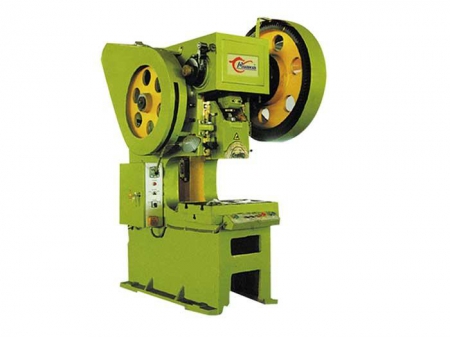
J23 J21 Power Press Machine
Request a Quote
The body of J23 J21 power press machine is a C-shape integral casting part, it iused for cutting, punching, blanking, bending, riveting and forming processes.
-
Nominal Pressure (kN)
100-800
-
Max. Closing Height (mm)
180-380
-
Closing Height Adjuster (mm)
35-100
-
Pole Distance (mm)
160-300
Parameters
| Item | |||||||
| Nominal Pressure (kN) | 100 | 160 | 250 | 400 | 630 | 800 | |
| Nominal Pressure Stroke (mm) | 4 | 5 | 5 | 6 | 6 | 8 | |
| Slipper Stroke (mm) | 50 | 60 | 70 | 100 | 100 | 120 | |
| Slipper Stroke Times (t/min) | 130 | 110 | 70 | 55 | 60 | 50 | |
| Max. Closing Height (mm) | 180 | 220 | 260 | 320 | 330 | 380 | |
| Closing Height Adjuster (mm) | 35 | 50 | 60 | 80 | 80 | 100 | |
| Distance Between Slipper Centre to Machine (mm) | 120 | 180 | 190 | 230 | 240 | 260 | |
| Work Bench Dimension | Front and Back (mm) | 240 | 300 | 320 | 400 | 450 | 480 |
| Left and Right (mm) | 360 | 450 | 530 | 650 | 710 | 750 | |
| Diameter of Blank-Holding Hole | Front and Back (mm) | 100 | 130 | 140 | 170 | 180 | 220 |
| Left and Right (mm) | 180 | 200 | 220 | 240 | 260 | 340 | |
| Diameter (mm) | 95 | 120 | 130 | 160 | 170 | 190 | |
| Slipper Underside Bore | Front and Back (mm) | 100 | 130 | 170 | 220 | 230 | 240 |
| Left and Right (mm) | 170 | 220 | 250 | 300 | 340 | 370 | |
| Size of Die Handle Bore | Diameter (mm) | 30 | 40 | 40 | 50 | 50 | 60 |
| Depth (mm) | 50 | 60 | 60 | 70 | 70 | 80 | |
| Pole Distance (mm) | 160 | 170 | 210 | 260 | 280 | 300 | |
| Distance between Bench to Guideway (mm) | 200 | 250 | 290 | 340 | 350 | 380 | |
| Pad Thickness (mm) | 35 | 45 | 50 | 80 | 80 | 90 | |
| Body Tilting Angle (°) | 30 | 30 | 25 | 25 | 25 | 25 | |
| Motor | Power (kW) | 1.1 | 1.5 | 2.2 | 4 | 5.5 | 7.5 |
| Rotational Speed (r/min) | 1410 | 1410 | 1440 | 1440 | 1440 | 1440 | |
| Dimension | Front and Back (mm) | 910 | 1100 | 1200 | 1500 | 1600 | 1750 |
| Left and Right (mm) | 650 | 780 | 900 | 1100 | 1150 | 1300 | |
| Height (mm) | 1560 | 1800 | 2050 | 2400 | 2480 | 2600 | |
| Weight (kg) | 420 | 760 | 1300 | 2600 | 3300 | 4500 | |
Component Description
The main components of the press include the following: Machine body, Transmission, Clutch, Slider, Brake, Control mechanism.