J21S Power Press Machine
Request a Quote
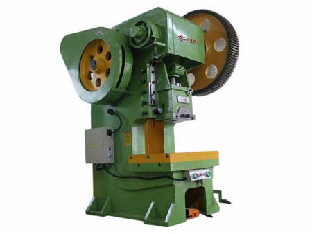
The J21S power press machine features a steel plate welding bed that has an outstanding vibration absorption. The throat features a certain depth and compact structure to ensure a safe operation.
-
Nominal Pressure (kN)
400-1250
-
Slide Stroke (mm)
100-140
-
Slider Stroke Number (t/min)
45-55
-
Maximum Shut Height (mm)
320-400
Parameters
| Parameter Name | |||
| Nominal Pressure (kn) | 400 | 1250 | |
| Nominal Working Stroke (mm) | 6 | 10 | |
| Slide Stroke (mm) | 100 | 140 | |
| Slider Stroke Number (t/min) | 55 | 45 | |
| Maximum Shut Height (mm) | 320 | 400 | |
| Closed Height Regulation (mm) | 80 | 100 | |
| Distance from the Centerline of the Slider to the Bed (mm) | 500 | 500 | |
| Table Size | Length (mm) | 400 | 660 |
| Width (mm) | 650 | 980 | |
| Worktable Blanking Hole Size | Length (mm) | 170 | 260 |
| Width (mm) | 240 | 400 | |
| Diameter (mm) | 160 | 210 | |
| Total Dimensions of Slider Bottom | Length (mm) | 220 | 360 |
| Width (mm) | 300 | 480 | |
| Die Handle Bore | Diameter (mm) | 50 | 70 |
| Depth (mm) | 70 | 90 | |
| The Distance between Two Columns of the Machine Body (mm) | 260 | 370 | |
| Net Distance between Worktable and Track (mm) | 340 | 430 | |
| Pad Thickness (mm) | 80 | 110 | |
| Motor | Power (kw) | 4 | 11 |
| Speed (r/min) | 1440 | 1460 | |
| Size of Shape | Length (mm) | 1800 | 2200 |
| Width (mm) | 1100 | 1500 | |
| Height (mm) | 2400 | 2800 | |
Component Description
The main components of the press include the following: Machine body, Transmission, Clutch, Slider, Brake, Control mechanism.