980nm EDFA Laser Module


- Kink-free operating power up to 200mW
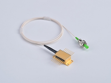
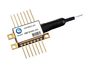
- epoxy-free, and flux-free 14-PIN butterfly package with
- SM Hi1060
- Fiber Bragg grating stabilization,
- Wavelength selection available
- Integrated thermoelectric cooler, thermistor, and monitor diode
- Excellent low power stability
- Next generation dense wavelength division multiplexing(DWDM) erbium doped fiber amplifiers(EDFA)
- Reduced pump-count EDFA architectures
- Very long distance cable television(CATV) trunks and very high node count distribution
The series 980nm pump module utilizes a planar construction with chip on subcarrier. The high power chip is hermetically sealed in a epoxy-free and flux-free 14-pin butterfly package and fitted with a thermistor, thermoelectric cooler, and monitor diode.
The series pump module uses FBG stabilization to ”lock” the emission wavelength. It provides a noise-free narrowband spectrum, even under changes in temperature, drive current, and optical feedback. Wavelength selection is available for applications that require the highest performance in spectrum control with the highest available powers. This module complies described in Telcordia GR-468-CORE requirement.
| Parameter | Symbol | Min. | Typical | Max. | Unit | Notes |
| Operating Case Temperature | Tcase | -20 | - | 75 | ℃ | - |
| Storage Temperature | Tstg | -40 | - | 85 | ℃ | 2000hours |
| LD Forward Current | If | - | - | 700 | mA | - |
| LD Reverse Current | Ir | - | - | 10 | uA | - |
| LD Reverse Voltage | Vr | - | - | 2 | V | - |
| PD Forward Current | IPD | - | - | -10 | mA | - |
| PD Reverse Voltage | VPD | - | - | 20 | V | - |
| TEC Current | Itec | - | - | 2 | A | - |
| TEC Voltage | Vtec | - | - | 3 | V | - |
| Fiber Bend Radius | - | 30 | - | - | mm | - |
| Relative Humidity | RH | 0 | - | 95% | - | Non condensing |
| Lead Soldering Time | - | - | - | 10 | Second | 260℃ |
| Fiber Axial Pull Force | - | - | - | 5 | N | - |
| Fiber Side Pull Force | - | - | - | 2.5 | N | - |
| Parameters | Sym | Min. | Typ | Max. | Unit | Notes |
| LD Threshold Current | Ith | - | 45 | 55 | mA | CW |
| Outpower | Pf | - | - | 200 | mW | If(BOL)< 470mA |
| LD Forward Current | If | - | - | 470 | mA | Pf=Rated Power |
| Kink Free Power | Pkink | 300 | - | - | mW | >=1.2*Rated Power |
| Kink Free Current | Ikink | >=1.2*If(BOL) | mA | [1] | ||
| LD Forward Voltage | Vf | - | - | 2.5 | V | Pf=Rated Power |
| Center Wavelength | λc | 973 | 974 | 975 | nm | Peak,Pf=Rated Power |
| 975 | 976 | 977 | ||||
| Peak Wavelength Turning | △λp/△Tamb | - | - | 0.02 | nm/℃ | T: FBG Temp. |
| Spectrum Width | △λ | - | - | 2 | nm | RMS@-13dB |
| Spectrum Stability | - | -0.5 | - | 0.5 | nm | Pf=Rated Power,t=60s |
| Monitor Responsivity | Im/Pf | - | 1 | 20 | uA/mW | VPD=5V,Pf=Rated Power |
| Monitor Responsivity Stability | - | - | - | 20% | - | @All Operating Temperature |
| Monitor Dark Current | Id | - | - | 50 | nA | VPD=5V |
| TEC Current | Itec | - | - | 1.5 | A | Tcase=75℃ |
| TEC Voltage | Vtec | - | - | 3 | V | Tcase=75℃ |
| TEC Modual Power Consumption | P | - | - | 5 | W | Tcase=75℃ |
| Power Stability >20mW 10-20mW 3.5-10mW | - | - | - | 0.2 0.5 1 | dB | Peak-to-peak,t=60s, DC to 50kHz sampling, TC=25℃ |
| Tracking Error | TE | -0.5 | - | 0.5 | dB | TC=-20~75℃,Refered to [2] |
| Thermistor Resistance | Rth | 9.5 | 10 | 10.5 | Kohm | Tstg=25℃ |
| Thermistor B constant | Bth | - | 3900 | - | k | Tstg=25℃ |
Notes:
[1] Kink Current is defined as the current which deviation of light versus current slop(dL/dI)from a linear fit is beyond +/-50%,Pkink>=1.2*Rated Power,Ikink>=If(BOL)*1.2
[2] Tracking error is defined at a given case temperature,it is the change in fibre power,at a constant monitor current, relative to the value measured at case 25℃
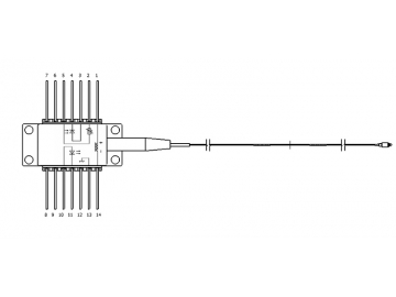
| PIN | DESIGNATIONS | PIN | DESIGNATIONS |
| 1 | TEC(+) | 14 | TEC(-) |
| 2 | Thermistor | 13 | Case Ground |
| 3 | PD Anode | 12 | NC |
| 4 | PD Cathode | 11 | LD Cathode |
| 5 | Thermistor | 10 | LD Anode |
| 6 | NC | 9 | NC |
| 7 | NC | 8 | NC |
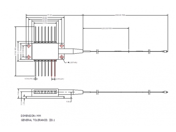
Dimensions are in millimeters. All dimensions are ±0.1mm unless otherwise specified. (Unit: mm).


")


")
")


 Light Source")

 Broadband Light Source")


