MG1814 Push Pull Mortise Lock

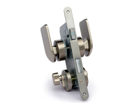

This model of push-pull mortise lock is designed with a brass cylinder and key. It is suitable for places with security requirements. The lock body shell is made of galvanized steel plate and the handle is made of aluminum alloy to ensure the firmness of the lock. Compared with other models of push-pull locks, this model has a higher strength and a better security. The bolt is made of plastic POM and zinc alloy to reduce noise and ensure a better mute effect. The surface treatment adopts Japanese advanced technology. Various tests are carried out in accordance with Japanese JIS standards to ensure the durability of the lock both from the appearance and structure. The lock has good compatibility and the size conforms to the European standard lock size; the center distance is 72mm; the distance from door edge to the center of the mounting hole for lever handle is 55mm; the center distance of the panel mounting hole is 38mm.
| No | Name | No | Name |
| 1 | Inner Lever Handle | 11 | Connecting Screw Bolt |
| 2 | Inner Panel for Lever Handle | 12 | Outer Cylinder Holder |
| 3 | Screw for Lever Handle | 13 | Inner Cylinder Holder |
| 4 | Inner Holder for Lever Handle | 14 | Plate for Lock Body |
| 5 | Lock Body | 15 | Screw for Lock Body |
| 6 | Outer Holder for Lever Handle | 16 | Cylinder Fixed Screw |
| 7 | Connecting Screw Bolt | 17 | Screw for Knob |
| 8 | Outer Panel for Lever Handle | 18 | Striking Box |
| 9 | Outer Lever Handle | 19 | Inner Knob Panel |
| 10 | Outer Cylinder Panel | 20 | Inner Knob |
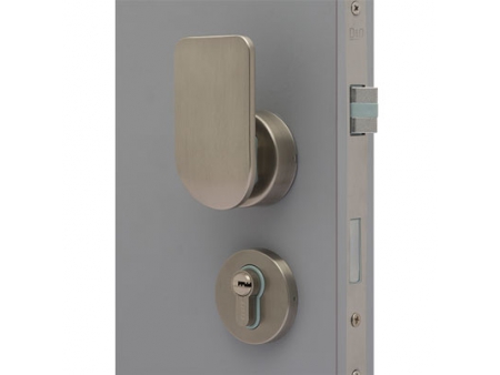
- Determine the direction of door opening. Put the lock body into the set hole and make sure the latch bolt is on the upper side and dead bolt is on the lower side. Make sure the inclined surface of the latch bolt is facing the direction of door closing (If the direction of inclined surface is wrong, pull the latch bolt out of lock body and rotate it by 180°. Then insert it back into the lock body), Install the front plate and tighten the screws.
- Inward opening door: push from outside and pull from inside. After installing the push-pull escutcheon panels, install the lever handles (fixed screws hole upwards) and then tighten the screws.
Outward opening door: push from inside and pull from outside. After installing the push-pull escutcheon panels, install lever handles (fixed screws hole upwards) and then tighten the screws.
(*Notice when installing push - pull escutcheon panels: make sure the push arrow on push plates is pointing upwards and the pull arrow on pull plates is upwards.) - Install cylinder thumbturn plates and tighten screws. Set the lock cylinder in the hole on the inside plate through the lock body and outside plate, and then fix the cylinder from the position of the armored front with cylinder screws.
- Install the striking plate on the corresponding position of the door frame and make sure that latch bolt and dead bolt can move in and out freely
- Test after installation: Push and pull the lever handles, press the latch bolt to the inclined surface direction of the latch bolt. If the latch bolt can work flexibly, the installation is completed. If not, please reset all components.