Four-Point Contact Ball Slewing Bearings

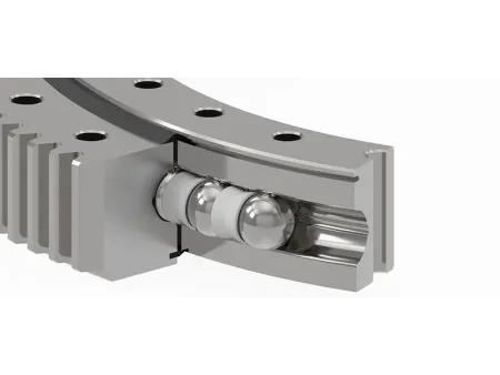

The four-point contact ball slewing bearing is designed with rolling elements and raceway for point contact. With compact structure and flexible rotation, the slewing bearing not only can simultaneously withstand axial load, radial load, overturning moment, but also can withstand a single direction load.
A notable advantage of this bearing type is its smaller cross-sectional size and lighter weight compared to other bearings, which doesn't compromise its ability to manage significant loads. Typically, these bearings are made from 42CrMo4 steel with the raceways hardened through an induction process to enhance durability. However, depending on the specific needs of the application, other materials can be used to meet different performance requirements.
LYXQL has developed significant expertise in manufacturing four-point contact ball slewing bearings, demonstrating advanced capabilities in both integrated and split structures. Our manufacturing capacity includes producing bearings with an outer diameter of up to 12 meters for integrated structures and up to 20 meters for split structures.
We are also equipped to handle a wide range of gear module sizes, with a maximum module of 45 and a minimum of 4.
(We are capable of customizing non-standard products based on specific customer requirements.)
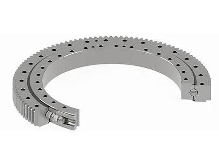
Slewing bearings are available in three main configurations: external gear, internal gear, and gearless designs. Each of these configurations consists of rings (both inner and outer), steel balls, spacers (also known as bearing cages), and seals. Depending on the application, additional dust-proofing features, such as dust covers or ash shields, can be added.
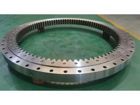
This type features gear teeth on the outer ring, making it suitable for applications where the gear mesh occurs externally. Due to the external positioning of the gears, this design generally requires more installation space compared to internal gear slewing rings.
The following specifications are from a previous version of our catalog. If you require the latest data or custom configurations, please don’t hesitate to contact us directly.
| Designations | Boundary dimensions | Bolt hole diameter | Structure dimensions | Gear parameters | Basic load ratings | Mass | ||||||||||||||||
| D | d | H | D1 | D2 | n1 | n2 | ⌀1 | ⌀2 | D3 | d1 | H1 | h | n3 | ф3 | m | Da | Z | b | x | Coa | ||
| mm | mm | mm | mm | mm | mm | mm | 104N | kg | ||||||||||||||
| D178794 | 694 | 470 | 77 | 630 | 500 | 18 | 18 | M16 | 18 | 567.5 | 564.5 | 64 | 13 | 6 | M10X1 | 6 | 696 | 114 | 60 | 0 | 157 | 93.1 |
| 1787/600G | 786 | 600 | 72 | 740 | 636 | 20 | 24 | M18X2.5 | 19 | 689 | 691 | 60 | 7 | 4 | ZG1/8in | 6 | 789 | 131 | 50 | 0 | 107 | 94.1 |
| 1787/674G2 | 853 | 674 | 70 | 825 | 709 | 34 | 23 | 20 | M20 | 764 | 768 | 59 | 10 | 2 | ZG1/8in | 7 | 889 | 125 | 50 | 0 | 183 | 89 |
| 1787/674G2K | 853 | 674 | 70 | 825 | 709 | 34 | 24 | 18 | 18 | 764 | 768 | 59 | 10 | 2 | ZG1/8in | 7 | 889 | 125 | 50 | 0 | 183 | 88.6 |
| 1787/710G2 | 894 | 710 | 67 | 845 | 744 | 8 | 8 | M10 | M10 | 798 | 806 | 58 | 9 | 3 | M10X1 | 6 | 924 | 152 | 55 | 0 | 179 | 107 |
| 1787/710G2K | 894 | 710 | 67 | 875 | 760 | 8 | 12 | M10 | M12 | 798 | 806 | 58 | 9 | 3 | M10X1 | 6 | 924 | 152 | 55 | 0 | 179 | 107 |
| 1787/710G2K1 | 894 | 710 | 67 | 865 | 744 | 20 | 20 | 13 | 13 | 798 | 806 | 58 | 9 | 4 | M10X1 | 6 | 924 | 152 | 55 | 0 | 179 | 107 |
| 1787/800G | 1050 | 800 | 90 | 1012 | 838 | 30 | 30 | 20 | 20 | 923 | 927 | 76 | 16 | 3 | M10X1 | 6 | 1092 | 180 | 60 | 0 | 215 | 217 |
| 1787/800GK | 1050 | 800 | 90 | 1012 | 838 | 30 | 30 | 20 | 20 | 923 | 927 | 76 | 16 | 3 | M10X1 | 6 | 1092 | 180 | 60 | 0 | 215 | 217 |
| 1788/1040G2 | - | 1040 | 80 | 1220 | 1080 | 30 | 30 | M16 | 17.5 | 1153 | 1157 | 70 | 10 | - | - | 10 | 1314.1 | 125 | 70 | 0 | 297 | 251 |
| 1787/1060G | 1335 | 1060 | 109 | 1295 | 1105 | 24 | 24 | M20 | 22 | 1198 | 1202 | 100 | 9 | 4 | M8X1 | 10 | 1388 | 138 | 80 | -0.6 | 501 | 407 |
| 1787/1075 | 1365 | 1075 | 120 | 1310 | 1130 | 36 | 36 | 26 | 26 | 1218 | 1222 | 105 | 15 | 4 | M8X1 | 8 | 1424 | 176 | 90 | 0 | 463 | 463 |
| 1787/1075K | 1365 | 1075 | 130 | 1310 | 1130 | 36 | 36 | 24 | 24 | 1218 | 1222 | 105 | 10 | - | - | 10 | 1420 | 140 | 120 | 0 | 463 | 550 |
| 1787/1075G2 | 1365 | 1075 | 120 | 1310 | 1130 | 36 | 36 | 24 | 24 | 1218 | 1222 | 105 | 15 | 4 | M10X1 | 10 | 1424.91 | 138 | 90 | 1.4 | 463 | 463 |
| 1787/1075G2K | 1365 | 1075 | 120 | 1310 | 1130 | 36 | 36 | M24 | 26 | 1218 | 1222 | 105 | 15 | 4 | M8X1 | 8 | 1424 | 176 | 90 | 0 | 463 | 463 |
| 1787/1330G2 | 1475 | 1330 | 82.4 | 1510 | 1362 | 24 | 24 | 18.5 | 18.5 | 1439 | 1445 | 70 | 12.4 | 6 | M10X1 | 9 | 1584 | 174 | 70 | 0 | 353 | 280 |
| 3-647G | 1407 | 1352 | 100 | 1370 | 1404 | 18 | 13 | M8 | M10 | 1390 | 1394 | 63 | - | 8 | 6 | 4.5 | 1449 | 320 | 60 | 0 | 216 | 143 |
| 1788/1410G2 | - | 1410 | 85 | 1590 | 1454 | 36 | 36 | M16 | 17.5 | 1524.6 | 1528.6 | 70 | 15 | - | - | 10 | 1676.4 | 160 | 70 | 0 | 395 | 312 |
| 1787/1640G | 2050 | 1640 | 160 | 1990 | 1710 | 30 | 30 | 28 | 28 | 1844 | 1856 | 140 | 20 | 2 | M14X1.5 | 10 | 2108 | 210 | 105 | -0.6 | 1118 | 1264 |
| 1787/1700 | 1945 | 1700 | 120 | 1900 | 1750 | 24 | 24 | M18 | 21 | 1825 | 1845 | 110 | 10 | 4 | M10X1 | 5 | 1970 | 392 | 35 | 0 | 405 | 516 |
| 1789/1700GM | 2052 | 1700 | 100 | 1980 | 1780 | 24 | 24 | 20 | M18 | 1878 | 1882 | 90 | 10 | 4 | M14X1.5 | 5 | 2080 | 414 | 50 | 0 | 551 | 678 |
| 1787/2650G2 | 2885 | 2650 | 100 | 2850 | 2700 | 48 | 48 | M20 | M20 | 2777 | 2781 | 80 | 10 | 6 | ZG1/4in | 12 | 2949.6 | 244 | 80 | 0 | 913 | 751 |
In this design, the gear teeth are located on the inner ring, allowing the gear mesh to occur inside the bearing. This configuration is more space-efficient, as it requires less installation space compared to external gear designs, making it suitable for applications where space is limited.
The following specifications are from a previous version of our catalog. If you require the latest data or custom configurations, please don’t hesitate to contact us directly.
| Designations | Boundary dimensions | Bolt hole diameter | Structure dimensions | Gear parameters | Basic load ratings | Mass | ||||||||||||||||
| D | d | H | D1 | D2 | n1 | n2 | ⌀1 | ⌀2 | D3 | d1 | H1 | h | n3 | ф3 | m | da | Z | b | x | Coa | ||
| mm | mm | mm | mm | mm | mm | mm | 104N | kg | ||||||||||||||
| 2788/850K | 976 | 850 | 80 | - | - | - | - | - | - | 916 | 919 | 80 | - | - | - | 2 | 916 | 456 | 20 | 0 | 174 | 117 |
| 3-646G2 | 1200 | - | 56 | 1170 | 1044 | 16 | 24 | 17.5 | 10.5 | 1088 | 1092 | 46 | 12 | 4 | M8X1 | 6 | 985 | 166 | 44 | 0 | 210 | 84.1 |
| 2782/1000GK | 1270 | 1000 | 100 | 1220 | 1050 | 24/2X2 | 24/2X2 | 17/M12 | 17/M12 | 1133 | 1137 | 85 | 15 | 2 | M10X1 | 6 | 972.6 | 164 | 70 | 0 | 384 | 322 |
| 2787/1210G2 | 1530 | 1210 | 122 | 1480 | 1260 | 40 | 40 | 26 | 26 | 1368 | 1372 | 108 | 12 | 4 | M10X1 | 10 | 1164 | 118 | 80 | 0 | 713 | 540 |
| 2787/1400GK | 1715 | 1400 | 110 | 1660 | 1460 | 24 | 24 | M20 | M20 | 1558 | 1562 | 95 | 15 | 2 | M12X1.25 | 6 | 1364.5 | 230 | 77 | -0.35 | 365 | 545 |
| 2787/1400GK1 | 1715 | 1400 | 110 | 1660 | 1460 | 24 | 24 | 23 | 23 | 1558 | 1562 | 95 | 15 | 2 | M10X1 | 6 | 1364.5 | 230 | 77 | -0.35 | 365 | 545 |
| 2787/1440 | 1780 | 1440 | 100 | 1730 | 1494 | 48 | 48 | 22 | M20 | 1618 | 1622 | 85 | 10 | 4 | M12X1.25 | 8 | 1400 | 177 | 50 | 0 | 503 | 545 |
| 2787/1440G | 1780 | 1440 | 100 | 1730 | 1494 | 48 | 48 | 22 | M20 | 1618 | 1622 | 85 | 10 | 4 | M12X1.25 | 8 | 1400 | 177 | 50 | 0 | 578 | 554 |
| 2768/1440G | 1780 | 1440 | 104 | 1730 | 1494 | 48 | 48 | 22 | M20 | 1613 | 1627 | 87 | 10 | 6 | M12X1.25 | 8 | 1400 | 177 | 52 | 0 | 578 | 555 |
| 2787/1525G2 | 1875 | 1525 | 140 | 1815 | 1585 | 42 | 42 | 29 | 29 | 1698 | 1702 | 122 | 17 | 4 | M12X1.25 | 16 | 1452.33 | 92 | 110 | 0.35 | 873 | 1019 |
| 2788/1712 | 2050 | 1790 | 112 | 2006 | 1847 | 36 | 72 | 22 | 22 | 1925 | 1926 | 92 | 12 | 18 | M10X1 | 16 | 1712 | 108 | 100 | -0.5 | 604 | 663 |
| 2789/2230 | 2488 | 2230 | 160 | 2445 | 2275 | 48 | 48 | M20 | M22 | 2337.5 | 2342.5 | 135 | 5 | 8 | ZG1/4in | 18 | 2144.25 | 121 | 145 | 0 | 1247 | 1114 |
| 2789/2240G2 | 2500 | 2240 | 140 | 2454 | 2280 | 56 | 56 | M24 | M24 | 2357.5 | 2362.5 | 115 | 5 | 8 | M14X1.5 | 18 | 2145.6 | 121 | 125 | 0 | 856 | 1161 |
| 2789/2735 | 2990 | 2735 | 160 | 2954 | 2770 | 48 | 48 | M20 | M24 | 2835 | 2845 | 135 | 5 | 8 | ZG1/4in | 22 | 2624.62 | 121 | 144 | 0 | 1559 | 1457 |
This gearless design features smooth inner and outer rings without any gear teeth. It is typically used in applications where gear interaction is not needed, offering a simpler and more straightforward solution.
The following specifications are from a previous version of our catalog. If you require the latest data or custom configurations, please don’t hesitate to contact us directly.
| Designations | Boundary dimensions | Bolt hole diameter | Structure dimensions | Basic load ratings | Mass | ||||||||||||
| D | d | H | D1 | D2 | n1 | n2 | ⌀1 | ⌀2 | D3 | d1 | H1 | h | n3 | ⌀3 | Coa | kg | |
| mm | mm | mm | mm | mm | 104N | ||||||||||||
| 116752 | 480 | 260 | 60 | 444 | 296 | 16 | 16 | 14 | 14 | 360 | 380 | 60 | - | - | - | 75.4 | 55 |
| 116752K | 480 | 260 | 60 | - | - | - | - | - | - | 360 | 380 | 60 | - | - | - | 75.4 | 58.6 |
| 176792 | 590 | 460 | 45 | 570 | 488 | 8 | 12 | M10 | 10 | 518 | 542 | 45 | - | - | - | 62.6 | 35.9 |
| 176792K | 590 | 460 | 45 | 570 | 488 | 12 | 12 | 10 | 10 | 518 | 542 | 45 | - | - | - | 62.6 | 36 |
| 176792K2M | 590 | 460 | 45 | 570 | 488 | 12 | 8 | 10 | 10 | 526 | 534 | 45 | - | - | - | 94.4 | 30.8 |
| 1167/530 | 780 | 530 | 60 | 740 | 560 | 20 | 20 | 17 | 13 | 645 | 665 | 35 | - | - | - | 112 | 103 |
| 1167/560 | 720 | 560 | 36 | 690 | 590 | 12 | 12 | 14 | 12 | 638.5 | 641.5 | 33 | 3 | - | - | 70.8 | 40.3 |
| 1167/560K | 720 | 560 | 36 | 690 | 590 | 12 | 32 | M12 | 16 | 634 | 646 | 36 | 3 | - | - | 70.8 | 39.2 |
| 1167/560M | 720 | 560 | 36 | 690 | 590 | 12 | 12 | 14 | 12 | 638.5 | 641.5 | 36 | 3 | - | - | 70.8 | 38.1 |
| 1168/560 | 780 | 560 | 60 | - | - | - | - | - | - | 645 | 668 | 60 | 3 | - | - | 224 | 103 |
| 11768/630 | 780 | 630 | 69 | - | - | - | - | - | - | 718 | 722 | 69 | - | - | - | 111 | 79.4 |
| 1167/700 | 900 | 700 | 36 | 860 | 740 | 12 | 12 | M16 | 17 | 796 | 804 | 36 | 3 | - | - | 179 | 60 |
| E787/760 G2 | 950 | 760 | 80 | 915 | 795 | 24 | 24 | 18 | M16 | 853.5 | 856.5 | 71 | 9 | 4 | M10X1 | 203 | 138 |
| 3-640 | 1000 | 775 | 64 | 948 | 802 | 24 | 12/12 | M12 | 13/M12 | 878 | 882 | 49 | 15 | 2 | M8X1 | 196 | 112 |
| 3-640K | 1000 | 775 | 64 | 948 | 802 | 24 | 12/12 | M12 | 13/M12 | 878 | 882 | 49 | 15 | 2 | M8 | 196 | 112 |
| 787/800 G | 1050 | 800 | 90 | 1012 | 838 | 30 | 30 | 20 | 20 | 923 | 927 | 76 | 16 | 3 | M10X1 | 215 | 192 |
| 71769/850Y | 1120 | 850 | 85 | 1074 | 924 | 12 | 12 | M20 | 22 | 995 | 1010 | 85 | - | - | - | 151 | 248 |
| 71769/850G2K | 1120 | 850 | 85 | 1074 | 924 | 12 | 12 | 17 | 22 | 999 | 1003 | 85 | - | - | - | 210 | 257 |
| 787/932G2 | 1200 | 932 | 120 | 1148 | 984 | 40 | 40 | 26 | M24 | 1064 | 1068 | 100 | 20 | 4 | G1/4in | 349 | 328 |
| 787/960G2 | 1165 | 960 | 90 | 1135 | 1040 | 36 | 36 | 18 | M16 | 1073 | 1077 | 78 | 14 | 6 | M10X1 | 249 | 202 |
| 787/1000G2 | 1250 | 1000 | 100 | 1206 | 1044 | 12 | 12 | 18 | M16 | 1123 | 1127 | 90 | 10 | 3 | M10X1 | 540 | 283 |
| 787/1260G2 | 1509 | 1260 | 90 | 1465 | 1315 | 36 | 36 | 22 | M20 | 1386 | 1389 | 70 | 14 | 2 | ZG1/8in | 378 | 274 |
| 71169/1400Y | 1820 | 1400 | 136 | 1750 | 1470 | 24 | 24 | 35 | 35 | 1608 | 1612 | 136 | - | 4 | M10X1 | 611 | 1114 |
| 71169/1400Y1 | 1820 | 1400 | 136 | 1750 | 1470 | 24 | 24 | 35 | 35 | 1608 | 1612 | 136 | - | 4 | M10X1 | 1070 | 1120 |
| 787/1440G2 | 1780 | 1440 | 100 | 1730 | 1494 | 48 | 48 | 22 | M20 | 1618 | 1622 | 85 | 15 | 4 | M12X1.25 | 503 | 533 |
| 787/1628G2 | 1927 | 1628 | 130 | 1875 | 1680 | 36 | 36 | 26 | M24 | 1774 | 1778 | 115 | 15 | 6 | G1/4in | 692 | 732 |
| 787/1700KM | 2000 | 1700 | 150 | 1950 | 1750 | 24 | 24 | 21 | 21 | 1842 | 1858 | 130 | 20 | 4 | M10X1 | 684 | 826 |
| KDL 900-6 | 1050 | 832 | 56 | 1020 | 862 | 12 | 12 | 18 | 18 | 942 | 946 | 45 | - | 4 | M6 | 227 | 52.5 |
| LY-Q007 | 485 | 275 | 55 | 453 | 307 | 16 | 16 | 18 | M16 | 381 | 386 | 50 | 5 | 4 | M10X1 | 87.2 | 43.7 |
| LY-Q007K | 485 | 275 | 55 | 453 | 307 | 16 | 16 | 18 | 18 | 381 | 386 | 50 | 5 | 4 | M10X1 | 87.2 | 43.7 |
| LY-Q020 | 440 | 240 | 55 | 400 | 280 | 18 | 18 | M20-7H | 22 | 340 | 342 | 50 | 5 | 3 | M10X1 | 78.2 | 34.7 |
Our products are widely utilized in wind turbines, marine equipment, tunnel boring machines, and construction machinery. Notably, our wind turbine products are well-known in the market, where we are recognized for offering turnkey solutions that cater to the unique needs of our clients.
What material is used for Four-Point Contact Ball Slewing Bearings, and what surface treatment is applied?
Are these bearings suitable for construction machinery manufacturers?
Absolutely. Our Four-Point Contact Ball Slewing Bearings are widely used across industries, including construction machinery (cranes, excavators), wind power, port equipment, and even medical devices.
What if I have limited space for bearing installation—what type do you recommend?
- With internal gear
- With external gear
- Without gear
For space-constrained applications, we recommend the internal gear version, as the gear meshing occurs within the bearing and requires less installation space than the external gear type.
What experience and certifications does your company have in this field?
Our main products include wind turbine main bearings, yaw bearings, pitch bearings, gearbox bearings, marine equipment slewing bearings, tunnel boring machine bearings and components, wind turbine shrink discs, and high-speed couplings.